Author Topic: Casting 0402 LEDs to make ditch lights some upidy HO guy said couldn't be done.  (Read 2760 times)

0 Members and 1 Guest are viewing this topic.

craigolio1

  • Crew
  • *
  • Posts: 2738
  • Respect: +2388
This is a build thread on how I do my ditch lights. It's dedicated to the HO guy who said, "You're crazy, that can't even be done in HO".  Paul it wasn't you.

About 8 years ago I tried to make lighted porch mounted ditch lights for a BC Rail SD40-2. I started with some brass I beam that I filed to a channel shape, and then attempted to shape fiber optics with a soldering iron into a Z shape. It sort of worked but I needed 5 sets and was too badly burned to make more than one. Then I discovered 0402 white LEDs.

My method had a lot of trial and error, and resulted in many failures, but ultimately with practice provided a cheap repeatable method with way fewer second degree burns.


1.  The epoxy I use, which is yellow but not thick enough to change the colour of the LEDs that shine through.


2. My masters.  I've made molds for ditch lights and in some cases headlights for CPR locos, BCR SD40-2, B36-7, 8-40CW, C44-9, CRS-20 #601, and not pictured here, the spot light style seen on CN SD40-2 (which I can also use on other locos like my BC Hydro SD and SW, VIA FP9, and others.


In the case of models where lights are mounted on the tops of walkways, I includ an .020 mounting pin on the bottom. It provides a path out for the wires and a strong attachment to the deck. Others that mount on pilots or head lights have the wire coming straight out the back.

3.  The mold after it is poured and comes out of the form.


4. LEDs. I solder them my self using the Ngineering soldering tool.  They available pre-soldered from various sources.  I have been using 32awg magnet wire and it works very well. I only have one colour so I have to test all the time through out installation to make sure I have the polarity right. It's good to test as you go anyway because, as I have learned, you can bugger these things up at any turn. It's best to find out right away and not after you have everything tied up just right.  Peteski has since got me into 38Awg magnet wire from Ngineering which is much more flexible and comes in red and green. It will make future projects much easier.  I was using Ngineering Super Incandescants but at $2 each it was getting costly. Especially since I have about a 50% failure rate between soldering and assembly. I now buy them on eBay 100 at a time from China for pennies. They are bright white, as you have seen, but are easily tinted with Tamyia Clear Orange. I like to tint after installation. I haven't done 601 yet but when I do it will allow me to be sure all 6 look the same. If you put on too much initially just wipe it off. You do see a little orange tint when the lights are off but I don't care. I will run my trains with the lights on and no one looks at the back!

5. The blob of epoxy. I put a little of each and try my best to make each blob the same size. If it's off it doesn't cure completely. 601s lights are actually a little flexible because the mixture was off a bit.  This turned out to be helpfull as they bend when you bump one. In the case of my CN SD40-2 they cured rock hard and just snapped off which meant redrilling/installing.  Did I mention my failure rate?  The CN SD took me 3 tries.


6. The mold filled with epoxy. I put it in with a tooth pick. Be sure to poke it into all of the holes and crevices. This stuff doesn't really flow.


Once filled to satisfaction, I squeegee the excess off by scraping across with the tooth pick.


8. The LEDs in the mold. I get the LED down inside by pushing it into the lens with the tooth pick. Then squish the wires in. After its straight scrape off the excess epoxy. Also get any that came out where the wires are. This prevents having to chip it off once cured which prevents proper installation and often results in cutting the wires. Ask me how I know. Notice that the wires have a hump shaped bend in them. This is there so that I can see the orientation of the LED in the mold. I had some that got turned sideways while pushing them in. More rejects. Once I squish the LED in, if the hump is turned to either side I know the LED isn't straight and I adjust it so the hump is straight up.


That's it. From soldering to final squeegee is about 15 minutes per set. Let them sit for a day or even two days to fully cure. Removing them too early ruins them. Even more rejects.

Put rejects in a pile for later to use as house lights or loading dock lights or what ever.

Here are the results.

BC Rail CRS20 #601


CN Expo 86 SD40-2w


CP Rail SD40-2
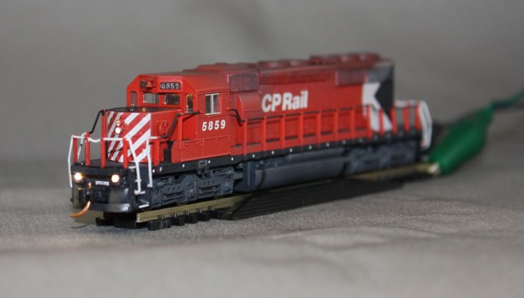


Thanks for your interest.  Please post your own successes of you try this method out.

Craig


« Last Edit: March 08, 2015, 10:08:32 PM by craigolio1 »

Scottl

  • Crew
  • *
  • Posts: 5307
  • Respect: +2619
Craig graciously made me a set of these LEDs and they are tiny!  I'm working towards installing them but you can see they have the right shape under a magnifier. 

Really nice work Craig and great of you to share your methods.  Next comes the layout engineering post  :ashat:

ryan_wilkerson

  • Crew
  • *
  • Posts: 1098
  • Respect: +209
    • ShastaRails.com
That's a cool method Craig! Thank you for documenting with photos and posting.

craigolio1

  • Crew
  • *
  • Posts: 2738
  • Respect: +2388
Thanks guys.

Scott I promise to start the bridge of this promotional process is done in May!

I should also mention that keen eyes may see a brass part in one of the masters. For the record before I cast it I had purchased enough of them for all of my models, which will now go unused because I'm casting them, and I contacted and received permission from the fellow before I cast them.

Please buy parts. These guys make those parts because they love the hobby and we couldn't make our models without them. I doubt any of them get rich making parts.

Craig.

peteski

  • Crew
  • *
  • Posts: 35336
  • Gender: Male
  • Honorary Resident Curmudgeon
  • Respect: +6665
    • Coming (not so) soon...
Nice writeup Craig!  It looks like the 5859 has the incandescent-white (or tinted) LEDs. That looks so much better than the HID-like stark bluish LEDs.

Could you also mention hwo you paint these?  Especially how you managed to keep the light from shining at the edges of the housing? Paint usually pulls away from he edges and it take multiple applications to get full (light-tight) coverage.

What brand/color paint did you use?  Airbrushed or brush-painted? How did you keep the paint from the "lens" areas?
. . . 42 . . .

ednadolski

  • Crew
  • *
  • Posts: 5084
  • Respect: +2098
Outstanding work Craig!   You've really raised the bar with these, thanks for sharing.  8) 8) 8) 8) 8)

 Ed

craigolio1

  • Crew
  • *
  • Posts: 2738
  • Respect: +2388
Thanks Guys.

Pete,

The CN loco used the bright white ones as seen in the pucture, but during assembly I snapped one off and they were replaced by Ngineering Super Incandescants. They do look awesome. The CPR SD used the bright white ones tinted with Tamyia Clear Orange after installation. 

On the CN loco I lit them up and then painted them with Polyscale (Steam Power?) Black. I just used a micro brush and kept applying until no light came through. If I got some on the lense I just scraped it off quickly before it dried.

The CPR loco was airbrushed with the same paint. I had tiny squares of masking tape over the lenses. After I removed them I touched them up with a micro brush.

On 601 I did it differently. They were so tiny I couldnt cut masking tape small enough. I air brushed them with Tamiya silver.  Then I just scraped the paint off the lenses. No problem. As you say they leaked light on the corners. Once I had them powered I brush painted them two more times and then they stopped leaking light. In the future I think I'll paint these black before applying a lighter colour like silver, or in the case of my future BCR units, red.

You can't see it in the picture but the rear headlight on 601 is pressed against the roof and makes it glow purple. I used one of the cast offs from the walkways on its side for the front and rear headlights. I will remove the shell and put a piece of black electrical tape in there. Those little 0402s put out a ton of light!
Craig.
« Last Edit: March 09, 2015, 01:01:49 AM by craigolio1 »

daniel_leavitt2000

  • Crew
  • *
  • Posts: 6445
  • Respect: +1427
All those in favor of moving this thread to "The Best Of Railwire"

I
American eyes, American eyes
View the world from American eyes
Bury the past, rob us blind
And leave nothing behind

mmagliaro

  • Crew
  • *
  • Posts: 6499
  • Gender: Male
  • Respect: +2014
    • Maxcow Online
Fine work, sir!   Mold, fine soldering, good ingenuity... and a really good looking result.

This may be of help:  That epoxy you used, shown in your photo, I'm sure a lot of people recognize.
That is Bob Smith Industries epoxy (http://www.bsi-inc.com/Pages/hobby/epoxies.html].
It is rebranded and sold in hobby shops all over (like yours, from
Canadian Hobbycraft).  I do like that stuff, and it's handy that you can buy it in 5, 15, and 30 minute cure
time formulations.
... just in case folks are wondering where they might get it.

craigolio1

  • Crew
  • *
  • Posts: 2738
  • Respect: +2388
Thank you, and thanks for the tip on the epoxy.

Craig.

peteski

  • Crew
  • *
  • Posts: 35336
  • Gender: Male
  • Honorary Resident Curmudgeon
  • Respect: +6665
    • Coming (not so) soon...
All those in favor of moving this thread to "The Best Of Railwire"

I

+1


Thanks for providing more construction details Craig.  So, you have no secret method to make the paint stick to the corners.   I was hoping.  :)

Speaking of BSI (Bob Smith Industries), I also use their CA glue and I absolutely love their CA glue accelerator. Nothing else comes even close to that accelerator (I have tried several other brands).

Such a funny name for an adhesives company. Bob Smith is as generic of a name as John Doe. I wonder if there really is a Bob Smith there.  :D 
. . . 42 . . .

craigolio1

  • Crew
  • *
  • Posts: 2738
  • Respect: +2388
Here are two shots of the lights I cast the other night, shown in the above posts.

Here is the pair as they come out of the mold. A little flash needs to be removed. You can see the LED in the top where the lense would be located.


Here is one of them lit up.


I'll paint it and post pics in between each coat so you (Peteski) can see light leakage.


Craig

craigolio1

  • Crew
  • *
  • Posts: 2738
  • Respect: +2388
I havn't gotten around to painting another set but I have tweaked the casting process a bit. I have trouble with the LEDs not sitting straight in the mould. They have no weight and the tiny wires dictate where they end up.

I decided to put a layer of .005" styrene on the back of the mould after casting to hold everything in place and it works very well. It allows me to control the wires while I clean up the end of the mould where the wire comes out. 

It also adds strength. The epoxy never really becomes rock solid because it's so thin and the styrene plate on the back adds stiffness.


I can even use this piece to grab with tweezers and assist in painting the fronts either with a brush or airbrush. Then paint the back by hand after I cut them off the back plate.

Craig