Author Topic: Best Of UP's N Scale Canyon Division Layout Build....  (Read 26516 times)

0 Members and 1 Guest are viewing this topic.

Sumner

  • Crew
  • *
  • Posts: 847
  • Gender: Male
  • Respect: +2411
    • My Home Pages....
Re: UP's N Scale Canyon Division Layout Build....
« Reply #135 on: December 26, 2025, 10:48:58 AM »
+2
Finally time to install turnouts and track on the upper level starting at the sawmill. Designed a .....


.... new servo mount based on the one I normally use. The normal one is installed from below using a couple tools you can print than allows a single person to install the servo in a couple minutes and have it dead center on where it needs to be to throw the throwbar. The problem on this part of the upper level is that the staging yard is 10 inches below the upper level so not much room to operate in placing a servo.

This mount is secured with a single screw and is easy to install from the side vs. having to be under it. I might use some of these on the lower level also it they work out well. I'll have install pictures soon and will probably put the print files up also. I printed the part of the mount that the servo attaches to with the resin printer using Siraya Tech Build resin. It is being tapped for 2-56 machine screws that hold the servo and the limit switches. The other parts that the single screw goes in were printed with a resin printer and a filament printer. That part also has 4 holes that are tapped and are used to connect the two parts together with 4-40 machine screws.

One or two limit switches can be attached to the mounts. Most of these will get one and it will be used for the frog polarity. Two will get 2 limit switches, one for frog polarity and the other to change the crossing's frogs polarity.


The first track going down for the upper level above.


Handlaying your track gives you many more options vs. most of the commercial track one can buy. Three 3-way turnouts will be used in this area to increase track lengths in different areas.

To be continued and a link to this whole build ( HERE ).

Sumner
Working in N Scale ---Modeling UP from late 40's to early 70's very loosely......

Under$8.00 Servo turnout Control --- 3D Printed Model RR Objects -- My Home Page

http://1fatgmc.com/RailRoad/RR Main/Link Page Menu.html

Sumner

  • Crew
  • *
  • Posts: 847
  • Gender: Male
  • Respect: +2411
    • My Home Pages....
Re: UP's N Scale Canyon Division Layout Build....
« Reply #136 on: December 29, 2025, 01:19:11 PM »
+3
Continuing with Sawmill Turnout Install -- Pt. 3.


Above jumpers have been added to power the rails just past the frog. I don't solder the turnouts to the tracks on both side but use rail joiners that do normally electrically connect these rails also to power (there are track feeds to all track sections). Not a great connection so these jumpers are there to send power in case the rail joiners aren't. There is also a wire to the frog for polarity changes to it. That wire connects to a limit switch on the servo mount. The switch is connected to track power resulting in the frog being powered with the correct polarity.


The servos are controlled with the $2 servo controllers above. I got the idea from Dave at trainelectronics.com. I expanded on it some by adding the 10K trimmer pot. This allows one to set the throw at both ends of the servo throw. It is easy to then adjust the throw so that the points just touch the stock rails and don't overpower the throw bar. Adding the two components only takes a couple minutes and ...


..... there are print files you can download ( HERE ) for a mount that the controller and 10K pot can be connected to. More info on this along with the print file links ( HERE ).


Fast tracks sells what they call QuickSticks for some turnouts that will speed up the 'adding ties' part of a turnout build and the ties will all be perfect and perfectly spaced but add quite a bit to the price of building a turnout. I used them a couple times but too expensive for how many turnouts I need and I like some 'imperfection' in the turnout. Not all 'real' track is perfect when it comes to the ties.

I buy their individual ties that come 500 to a bag  and even though they have gone up they save me a lot in building a turnout. If you stray from the most popular turnouts there are no Quick Sticks for what you are building. I designed and print some jigs, shown above, that help place ties under straight and curved turnouts. They speed things up but expect to re-glue a few as some will fall off cutting them to length and in handling. This is the part of the turnout build I like least but getting quicker at it. Links to the 3D printed tie jigs ( HERE ) & ( HERE ).


I gave up on using Pliobond which Fast Tracks recommends and use CA instead. It can be tricky to work with also. Be careful around the points so that you don't glue them where they won't throw. At times I slide these in once the turnout is down and glue them to the roadbed and not to the turnout. I have a lot of info on my site about turnout construction ( HERE ) and there are other resources out there also.

To be continued and a link to this whole build ( HERE ).

Sumner
Working in N Scale ---Modeling UP from late 40's to early 70's very loosely......

Under$8.00 Servo turnout Control --- 3D Printed Model RR Objects -- My Home Page

http://1fatgmc.com/RailRoad/RR Main/Link Page Menu.html

Sumner

  • Crew
  • *
  • Posts: 847
  • Gender: Male
  • Respect: +2411
    • My Home Pages....
Re: UP's N Scale Canyon Division Layout Build....
« Reply #137 on: January 09, 2026, 10:08:33 AM »
+1
...... continuing on with turnouts and installing servos.


Mounted a number of $2 servos to the new style 3D printed servo bracket. Then centered the wire to the throwbar with the $2 servo controller prior to installation (couple minutes). Once the servo is mounted under the turnout the controller is used to adjust the throwbar throw so that the points just touch the stock rails and aren't overpowered by the servo (another couple minutes).


This mount was designed to be installed from the side of the layout when you can't get directly under the turnout. Here the lower level staging yard is 10 inches under the servos and in the way of mounting them from directly below. This mounting can be done in a couple minutes from the side of the layout and the throwbar piano wire will end up perfectly centered under the throwbar hole.

The extended round area on the top of the mount goes up into a 3/8" hole centering the throwbar wire. Then the single screw holds the mount & servo in place since it can't pivot with the round area up in the hole. I'll probably start using these about everywhere since one doesn't need to go under the layout to mount the servo if you can reach where the mount will go from the side. I'll put another page up with all the details and will show how easy these mounts are to use for servo installs.

13 turnouts with wood ties added and painted installed along with servos.  4 to go.

To be continued and a link to this whole build ( HERE ).

Sumner
Working in N Scale ---Modeling UP from late 40's to early 70's very loosely......

Under$8.00 Servo turnout Control --- 3D Printed Model RR Objects -- My Home Page

http://1fatgmc.com/RailRoad/RR Main/Link Page Menu.html

Sumner

  • Crew
  • *
  • Posts: 847
  • Gender: Male
  • Respect: +2411
    • My Home Pages....
Re: UP's N Scale Canyon Division Layout Build....
« Reply #138 on: January 15, 2026, 02:03:03 PM »
+1
Layout Help -- Ed's Work Pt 1....

Time to introduce UP's N scale Canyon Division's newest and only current additional worker, Ed. A little bit about ED.

Ed and I met for the first time a couple months back. He is a Blanding, UT native. I've been here about 30 years and we had never met even thought the population is under 4,000. Dottie, my wife, goes to an exercise class and met Ed and his wife there and introduced him to me. We hit it off right away and he has helped a lot on the layout in the last couple months. This is his first model railroad experience and has been enjoying it.

He just pasted mid 60's and drove truck for over 30 years delivering petroleum products throughout the western states and is now retired. He lost a lower leg to diabetes a couple years ago and it is painful to stand for longer periods for him. As with any layout there is a lot that can be done sitting and he has been busy making trees, painting vehicles and helping soldering and assembling electrical components for the layout. The following is some but not all of his work.


Ed and I started looking on the internet for vehicles that he could paint and that we would need for various scenes. We then ordered vehicles from igMakes on eBay (above) and ....


..... OutLand Models (above) and ....


..... GHQ and Royal Models (above). They all have good models with different pricing and skill level needs for assembly. IgMakes and Rasputen N Scale Vehicles are the least expensive. They are nice with little or no assembly needed with lots of cars and some trucks to fit our time period of pre-mid 70's. The other's had more in the way of commercial vehicles with different degrees of assembly required. The layout is dominated by industrial scenes so we need trucks. There is the edge of a small town where you would see more cars and workers at some of the industries would go to work in cars and pickups.


Ed started with the hardest model to assemble, the logging truck shown above from GHQ. I wouldn't of gotten it together probably. Lots of very small detailed parts. Ed got the job done even with shaking hands.

More on 'shaking hands'. When I started back into N scale a few years back I wondered if I had made a mistake since I also had shaking hands at times and everything seemed so small. I found that over time as I worked more and more with assembling small items and painting them the shaking got less and less. Ed has found this also to be true and he says the shaking has decreased a lot just in a couple months. If this is a problem you have maybe try sticking it out a little longer and see if N scale can help in that department with you also. I'm sure its not a fix for everyone but hopefully for some of you.


Above are a number of cars from Rasputan-N Scale Vehicles that are quite nice for the price (as low as $4 each). Contact him at BFedoroff@twmi.rr.com for a long/lots of cars list. He also posts on TrainBoard and Railwire.


More info and a print file link for the warren truss road bridge ( HERE ).


Ed's made a lot more trees that what is shown above. These will go on the sawmill scene along with some others.


It's nice to have someone else working on the layout......thanks Ed for the work you've done and will be doing. To be continued and a link to this whole build ( HERE ) .

Sumner
« Last Edit: January 15, 2026, 02:12:20 PM by Sumner »
Working in N Scale ---Modeling UP from late 40's to early 70's very loosely......

Under$8.00 Servo turnout Control --- 3D Printed Model RR Objects -- My Home Page

http://1fatgmc.com/RailRoad/RR Main/Link Page Menu.html

Sumner

  • Crew
  • *
  • Posts: 847
  • Gender: Male
  • Respect: +2411
    • My Home Pages....
Re: UP's N Scale Canyon Division Layout Build....
« Reply #139 on: January 18, 2026, 11:44:34 AM »
+4
Sawmill Turnout Install -- Pt. 4....

Finished the hard part of the track laying by the sawmill, the turnouts and crossing. This took a little longer than expected. I already had some of the turnouts built but not tested on the turnout tester. They also all need ties and the ties painted. Also added wiring to power the two short inner rails past the frog and dropped a wire from the frogs so that they could receive the correct polarity from the micro/limit switches on the servo brackets.

Needed to wire a number of the $2 servo controllers so that they can control the limit of the servo throw in both directions, limiting the possibility of over powering the turnouts point rails. Designed a new servo bracket that I love and now will use most everywhere. It mounts in a couple minutes dead center under the hole in the throwbar. One doesn't need to go under the layout to mount it. You can do all the mounting from the side of the layout as long as the reach to the bracket isn't to far. If you do have to go under it is really simple to mount with one Sheetrock screw.

The images should tell the rest of the story....................


.


.


.


.


Above I still needed to pull the two curved turnouts back out and add wiring to them and paint the ties.


The remainder of the track to lay here is all ME code 55 flex. That should go pretty fast but then there is a lot of wiring that needs to go in.


Two turnouts to the crossing will be thrown by one switch on the control panel. When thrown for the route to the crossing the micro limit switches on their servo brackets will not only change the turnout's frog polarity but also the polarity of the crossing.


One can save a ton of money building their turnouts and can build ones you just can't buy.


.


I'll soon have more info and print file links up on the really easy to use servo brackets above.

To be continued and a link to this whole build ( HERE ).

Sumner
Working in N Scale ---Modeling UP from late 40's to early 70's very loosely......

Under$8.00 Servo turnout Control --- 3D Printed Model RR Objects -- My Home Page

http://1fatgmc.com/RailRoad/RR Main/Link Page Menu.html

Sumner

  • Crew
  • *
  • Posts: 847
  • Gender: Male
  • Respect: +2411
    • My Home Pages....
Re: UP's N Scale Canyon Division Layout Build....
« Reply #140 on: January 27, 2026, 01:57:10 PM »
+2
Sawmill Track & Wiring -- Pt. 1

While installing the turnouts and crossing I put some track in to help locate them. Below I'm finishing up the track for this section of the layout. I ran out of steam getting this track in and it took longer than I was hoping for. Age is catching up and doing a task like this is down to 3 or 4 hours a day at the most. Then if I don't procrastinate I'll get something done at the workbench. Always something I can work on there.


I put more tracks in this scene than would ever be needed in a real world situation. I want a place to leave some unload rail cars, maybe a smaller engine just to work the mill and just got a N scale Tichy Track rotary snowplow that I hope to add a motor to for the blade and some sound effects. Since this is the high point on the layout it might be kept here.


I continue to lay track with the DAP Dynaflex 230. Goes on white but dries clear and just need a thin film to hold the track down. I tried the soup can 'hold-down' method but didn't like it that much. I find that the push pins also help to align the track where I want it besides doing a good job of holding it down while I let the caulk setup overnight.


I want to be able to remove my turnout if I feel that is necessary to work or replace them. Most are held by the adjoining track that is caulked down. Where I have a couple back to back I've started putting in an end tie or two with a very small hole for a M2 screw that goes down into the foam board. Once painted the screws are not very noticeable unless someone is really paying attention and so far that hasn't been the case with visitors and I'm a function first guy. I wouldn't use them on say a diorama that gets a lot of 'local' focus.


.


.


Instead of spending hundreds of dollars on turnouts, some of which aren't even available, I've got about a hundred dollars into them. Also about another hundred into servos, brackets, servo controllers and a control panel for this scene.


Ed has been coming in 2-3 days a week for a few hours each day and lately assembling and painting vehicles. Info and print file links for the end of track prints ( HERE ).


Started wiring so will post info and images about that next.


.


You can find info and print file links for all the sawmill parts ( HERE ). Lots of work still needed to make it into a finished or even a partially finished scene.

To be continued and a link to this whole build ( HERE ) .

Sumner
Working in N Scale ---Modeling UP from late 40's to early 70's very loosely......

Under$8.00 Servo turnout Control --- 3D Printed Model RR Objects -- My Home Page

http://1fatgmc.com/RailRoad/RR Main/Link Page Menu.html

Sumner

  • Crew
  • *
  • Posts: 847
  • Gender: Male
  • Respect: +2411
    • My Home Pages....
Re: UP's N Scale Canyon Division Layout Build....
« Reply #141 on: February 08, 2026, 12:49:37 PM »
+2
Ed's Vehicles...

Ed has been really busy assembling and painting vehicles and also some end-of-track prints for the layout.


.


More info and print file links for the end-of-track prints ( HERE ).


.


.


.


.


Thanks Ed for all the work you have put in for the layout.

To be continued and a link to this whole build ( HERE ) .

Sumner
Working in N Scale ---Modeling UP from late 40's to early 70's very loosely......

Under$8.00 Servo turnout Control --- 3D Printed Model RR Objects -- My Home Page

http://1fatgmc.com/RailRoad/RR Main/Link Page Menu.html

dandopinski

  • Crew
  • *
  • Posts: 219
  • Respect: +454
Re: UP's N Scale Canyon Division Layout Build....
« Reply #142 on: February 08, 2026, 10:29:23 PM »
+1
Fantastic stuff! So many useful ideas.

Sumner

  • Crew
  • *
  • Posts: 847
  • Gender: Male
  • Respect: +2411
    • My Home Pages....
Re: UP's N Scale Canyon Division Layout Build....
« Reply #143 on: February 15, 2026, 12:08:48 PM »
0
Soldering Track Drops...

With the track down for the sawmill scene area it was time to do a lot of wiring. There are track drops from all sections of track since I don't solder the rail joiners between the turnout ends and the ME code 55 flex track. With 17 turnouts in this area that meant a lot of wires running to them, to the frog polarity servo bracket limit switches and to the flex track between the turnouts (over 40 track drops).
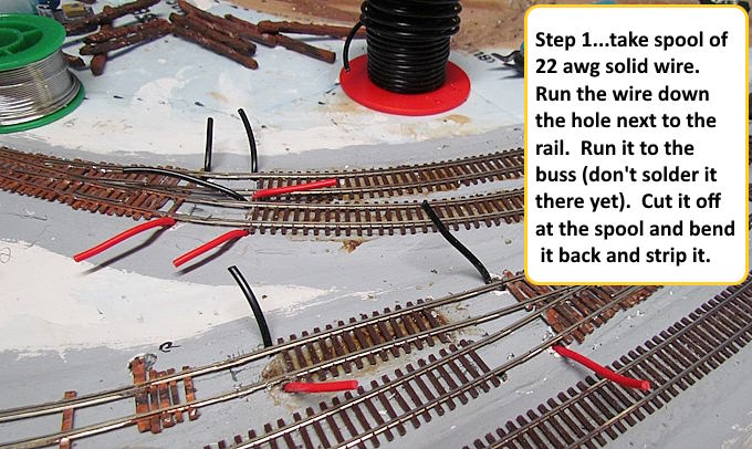
 

I drill holes just big enough for the 22 awg solid wire I use. Then from the wire spool I run wire down through the hole. Reach under and pull it to the side of the layout where it will later be soldered to the buss. Cut the wire off, pull it out from the hole a bit, bend it over and strip about 1/2" of the insulation off.
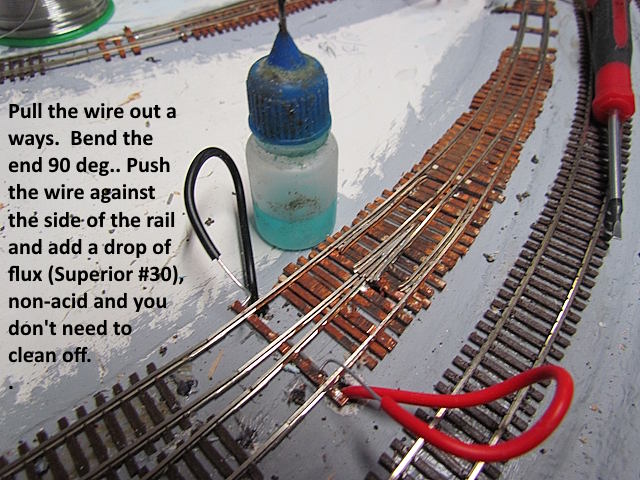
 

I pull it out further and put a short 90 degree bend in the end and bend it back so that it will contact the side of the rail easily. I hold the wire to the rail and put a small drop of Superior #30 liquid flux on the wire/rail joint. The flux is crucial as the solder will flow very quickly onto the wire/rail joint when the soldering the joint. This is not an acid flux and doesn't have to be cleaned afterwards but if you are using one that does need to be cleaned be sure and do that. I love this flux and use it for all my electrical projects. A little hard to find but do a Google search.
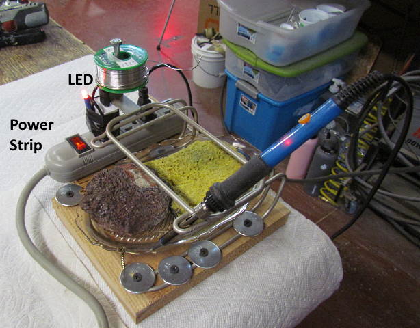
 

In the next step I'll solder the wire to the rail but first. Between almost every solder joint I make, here or on other projects, I clean the iron right before it. I dip the hot iron in one of the small tins of tip cleaner (not shown above) and then wipe it on the wet sponge. The tip should then be shiny silver. It is isn't you are going to have a hard time soldering. Again, I do this for every solder joint just before using the iron. It is a lot of quick cleaning but pays off in easy soldering. I've tried other tip cleaning methods but the sponge still works best for me.

Also I have more expensive irons but these are only $15 on the internet and work great and extra tips are really cheap and quick to replace. Once you can't get solder to stick to your iron change to a new tip. I use a 100 watt iron for these track drops so that I'm on and off in a second or less which then doesn't melt the ties unless you touch them (which I do occasionally). I use a 60 watt for all my other projects. I keep both irons on 'full' hot so that the solder joint time is very short. This keeps the ties or other components from overheating.

I'm using .8mm rosin core solder for the drops and .6mm rosin core for everything else.
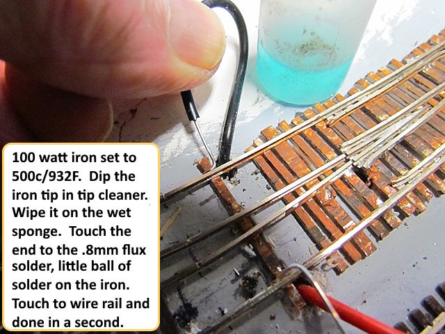
 

With the wire pre-bent and the flux on the wire and rail and a clean iron with a small drop of solder on the tip the soldering will happen in one to two seconds. Hold the wire on the rail. Touch the iron tip to the end of the solder for just a touch of solder. Push the tip with the drop of solder on the tip against the wire/rail and the solder should flow almost instantly. As soon as you see it flow pull the iron away. No melted tie unless you touched.

With an iron at a lower temperature you will be on the joint a longer time and the heat will transfer to the tie.
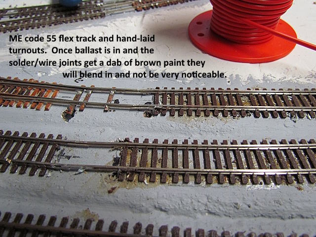
 

If you want to solder to the bottom of the rail you could do that also. Slightly different steps. I have too much to do to take that approach and with a drop of paint on the solder joint I can't imagine very many visitors ever seeing the drops. They are too busy looking at everything else. At least that seems to be the case so far.
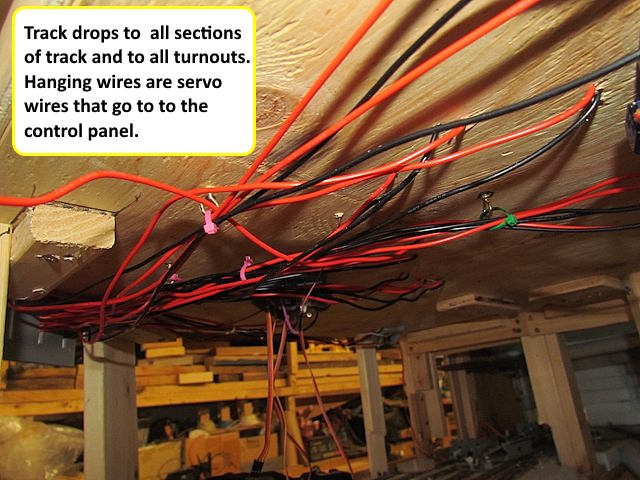
 

Above you can see half the drops in the sawmill scene. These go to solder pads ......
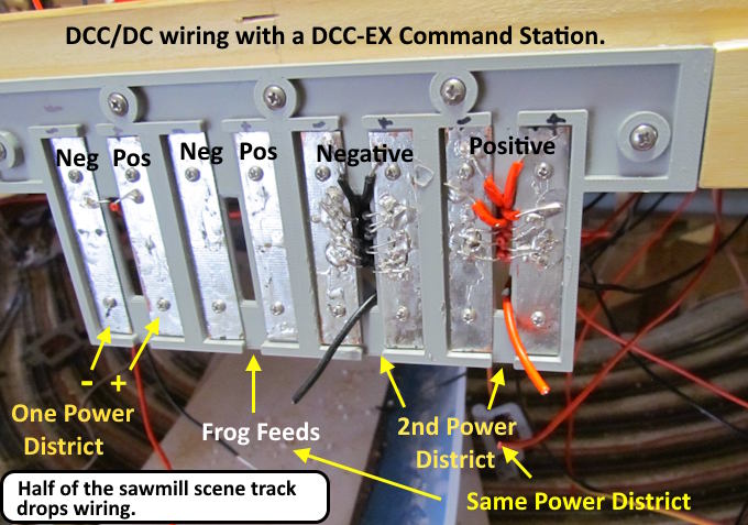
 

..... on one side of the layout with another set of solder pads on the other side. The outside main track here is in a different power district that the majority of the track in the scene. Since a DCC-EX Command Station can put out DC and DCC to different districts (8 in my case) at the same time I'll be able to run a DC loco on the outer main track and one or more DCC loco in the rest of the scene at the same time.

I didn't go with buss wires...
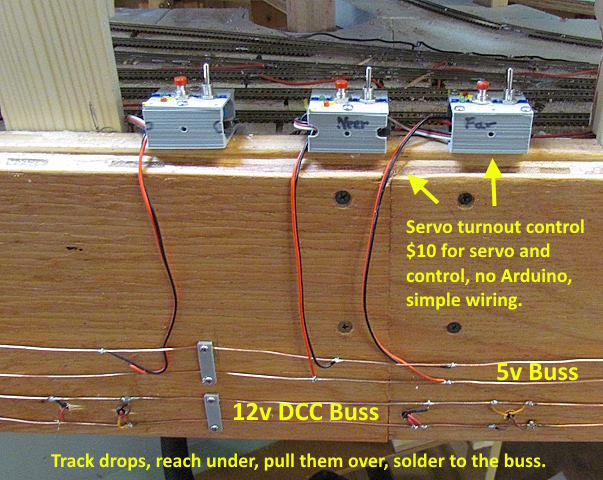
 

.... like I did on the lower level (above and ( HERE ) ) as the fascia isn't wide enough on the upper level here so that there is good access to the hidden staging below. The solder pads work well as I can connect a lot of wires together and the DCC from the command station in a very small area.

To be continued and a link to this whole build ( HERE ) .

Sumner
Working in N Scale ---Modeling UP from late 40's to early 70's very loosely......

Under$8.00 Servo turnout Control --- 3D Printed Model RR Objects -- My Home Page

http://1fatgmc.com/RailRoad/RR Main/Link Page Menu.html

Sumner

  • Crew
  • *
  • Posts: 847
  • Gender: Male
  • Respect: +2411
    • My Home Pages....
Re: UP's N Scale Canyon Division Layout Build....
« Reply #144 on: February 16, 2026, 01:01:49 PM »
+2
U.P. N Scale Rotary Snow Plow....

Recently Norm on nscale.net post a build of a rotary snow plow that he had done ( HERE ) . The blade spins and he is using a sound decoder for sound. I thought this would make an interesting project so ordered the Tichy Trains N scale rotary snow plow that he had used.

He used the stock frame and mounted an electric motor on it. I designed a frame with fusion where the motor sits a bit lower to align with the shaft going to the blade and has a bearing block that holds two 2mm ID ball bearings. I got that working but then decided to see if I could design a rotary snow plow around one that U.P. had. It was build in 1922 and retired in 1969. It also had been converted from coal fired to oil fired in '49-50'.

The following is Part 1 of the build.


I found a drawing of the snow plow on utahrails.net. A great site if you are into Union Pacific. I used it to try and get the model somewhat accurate, maybe 80%-90%. I inserted the drawing as a 'canvas' into Fusion and re-calibrated it to N scale size.


I couldn't find a drawing for the left side but from pictures and a model of the snow plow came up with I thought was close (above).


.


Above is the first print. It came out pretty good but there are some problem areas that need to be addressed. Not much and I think I know what I need to do (check back or see if the next page has the corrections).


The ladder was only attached to the body at the top and bottom. The print was done at 45 degrees and it sagged while printing. I believe a couple more attach points between the bottom and top on the back side of the ladder will fix that.


.


Above the blade is sticking out a bit as it was a little oversize in diameter. The one, bottom right, should fix that.


The shrink wrap (above) worked well as a coupling. I might stick with it or look at designing a 3D printed coupling.


Above the shell is sitting on top of the frame and front wall. It is setup to work with MT trucks.


The new model looks smaller above but was further from the camera. They are almost exactly as long (the new one is a touch longer actually). More to follow in a couple days hopefully.

To be continued and a link to this whole build ( HERE ) .

Sumner
Working in N Scale ---Modeling UP from late 40's to early 70's very loosely......

Under$8.00 Servo turnout Control --- 3D Printed Model RR Objects -- My Home Page

http://1fatgmc.com/RailRoad/RR Main/Link Page Menu.html

Jesse6669

  • Crew
  • *
  • Posts: 1052
  • Respect: +2676
Re: UP's N Scale Canyon Division Layout Build....
« Reply #145 on: February 16, 2026, 02:07:33 PM »
0
Very cool project!  Those handrails might just need slightly larger diameter, or could be printed as a separate piece. 

Sumner

  • Crew
  • *
  • Posts: 847
  • Gender: Male
  • Respect: +2411
    • My Home Pages....
Re: UP's N Scale Canyon Division Layout Build....
« Reply #146 on: February 16, 2026, 02:41:47 PM »
+1
Very cool project!  Those handrails might just need slightly larger diameter, or could be printed as a separate piece.

Thanks, I think they will be OK.  I printed at 45 degrees and they were sagged on the build plate.  I just added connections behind the rung ends back to the shell.  I'll see if that takes care of them.  I also added them to the shorter gragirons even though they printed ok on one side.  Will see how they look next print.  Still changing some other items I didn't like.

Sumner
Working in N Scale ---Modeling UP from late 40's to early 70's very loosely......

Under$8.00 Servo turnout Control --- 3D Printed Model RR Objects -- My Home Page

http://1fatgmc.com/RailRoad/RR Main/Link Page Menu.html

Sumner

  • Crew
  • *
  • Posts: 847
  • Gender: Male
  • Respect: +2411
    • My Home Pages....
Re: UP's N Scale Canyon Division Layout Build....
« Reply #147 on: February 26, 2026, 02:48:54 PM »
+4
Sawmill Track and Wiring -- Pt. 3....

Getting close to being able to run a loco and a couple cars around the sawmill complex. I can do that now except I can only throw one turnout at a time with the servo tester/adjuster connected only to that turnout.


.


.


.


.


.


.


.


Next up is getting the control panel wired and installed. Been also spending way to much time on the rotary snow plow.


About 4 prints into it at this point but think that it is where I want it now. Next up will be designing a tender for it. In 1949 these plows were changed from being coal fired to burning fuel oil.

Earlier in the 40's U.P. had bought some N&W 2-8-8-2's along with their tenders. They were decommissioned in '49 and the coal bins on two of the tenders were outfitted with tanks for the oil. I've been able to find similar tenders on eBay but ordered twice and had my money refunded twice as the sellers couldn't find them in their stock. So I've decided to design and print those also. I was able to pickup some 3 axle trucks that I can use under the tenders. So tender design is next.


A short overview of the U.P. rotary snow plow at this point ( HERE ).

To be continued and a link to this whole build ( HERE ) .

Sumner
Working in N Scale ---Modeling UP from late 40's to early 70's very loosely......

Under$8.00 Servo turnout Control --- 3D Printed Model RR Objects -- My Home Page

http://1fatgmc.com/RailRoad/RR Main/Link Page Menu.html

Scottl

  • Crew
  • *
  • Posts: 5293
  • Respect: +2594
Re: UP's N Scale Canyon Division Layout Build....
« Reply #148 on: February 26, 2026, 02:53:42 PM »
0
That is a lot of modeling goodness in one post.  Outstanding, as usual!

Sumner

  • Crew
  • *
  • Posts: 847
  • Gender: Male
  • Respect: +2411
    • My Home Pages....
Re: UP's N Scale Canyon Division Layout Build....
« Reply #149 on: March 01, 2026, 11:27:42 AM »
0
Sawmill Track Wiring Pt. 4 & Couplers....+

This is the first control panel that I've built and as I write this not quite done yet so can't say if I'm happy with the results or not at this point. If you have come into the build at this point and ....


....... are interested in how it was designed and printed go ( HERE ) .

The panel will use .......


..... a number of solder pads for wire connections. I like making these as the PCB material is cheap on eBay and I can get a lot of connections into a small area and it is easy and quick to solder wires the pads. I've found that it is really easy/quick to cut the isolation gaps with the right angle Dremel tool above with a diamond grit cutting disc . I then clean the cut up with the triangular file.


Servos and the servo controller I use have three wires from the panel to the $2 controller and on to the servo. The panel will control 17 servos but there are two locations where the toggle switch on the panel will throw 2 servos/turnouts. Across the top are 15 sets of three pads that the wires to the servo controllers will solder to.


The panel will also control track power to 4 sections of track where an engine can be parked and the power turned off.


Track power in to power the 4 tracks and power out to the tracks will solder onto 5 pads just below the row of servo pads. The toggle switches will only be controlling the power to one side of these tracks, which is all that is needed to make them dead or alive.


Above the yellow, blue and red wires are for the four on/off track power sections. With that wired I started wiring in all of the red LED's that will indicate if the route chosen is the divergent route of the turnout being controlled. I'm testing them as I wire them with alligator clips to the toggle switch and to one of the ground pads. Some of the other solder pads are 5v negative & positive pads used for the servo and LED wiring.

The round objects next to the toggle switches are on/off push button switches. You throw the toggle and the appropriate LED lights. Then you push the button switch and the turnout throws. I do this so that the servos are only powered while throwing. Cuts down of power needed and also I don't like the servos powered all of the time. The layout will end up with over 70 servo controlled turnouts so that would be a lot of servos powered at the same time.


I got a day (not 8 hours) into making the solder pads and wiring to this point. Probably two more partial days to finish.

While I've been doing this Ed has been also working. He normally comes 2-4 day a week in the afternoon for a couple hours.


I mentioned to him that I had a lot of couplers that need assembly. I showed him how to do it on a couple and struggled since it had been a couple years since I'd done it myself. I told him to think about it as he headed home for the day. I put 4 more together and finally got back into a rhythm but felt a little guilty asking him to consider doing this.


He came back the next day and said he wanted to try. He sticks with things. Pretty soon he was turning couplers out and came back the next day also and had 20 pairs (40 couplers) finished after two short days of work.


When I put some of these together a couple years ago I designed and printed the assembly aid above. It really makes the job easier by far. More info and print file links ( HERE ) .

To be continued and a link to this whole build ( HERE ) .

Sumner
Working in N Scale ---Modeling UP from late 40's to early 70's very loosely......

Under$8.00 Servo turnout Control --- 3D Printed Model RR Objects -- My Home Page

http://1fatgmc.com/RailRoad/RR Main/Link Page Menu.html