Author Topic: Best Of UP's N Scale Canyon Division Layout Build....  (Read 26519 times)

0 Members and 1 Guest are viewing this topic.

Sumner

  • Crew
  • *
  • Posts: 847
  • Gender: Male
  • Respect: +2411
    • My Home Pages....
Re: UP's N Scale Canyon Division Layout Build....
« Reply #120 on: November 07, 2025, 08:15:24 PM »
+4
Spackle, Spackle, Paint – Pt. 4....

Finishing up this stage of the scenery work on the south side of the layout.


.


.


.


.


.


.


.


.


For a YouTube tour of the layout at this stage .....


To be continued and a link to this whole build ( HERE ).

Sumner
Working in N Scale ---Modeling UP from late 40's to early 70's very loosely......

Under$8.00 Servo turnout Control --- 3D Printed Model RR Objects -- My Home Page

http://1fatgmc.com/RailRoad/RR Main/Link Page Menu.html

Sumner

  • Crew
  • *
  • Posts: 847
  • Gender: Male
  • Respect: +2411
    • My Home Pages....
Re: UP's N Scale Canyon Division Layout Build....
« Reply #121 on: November 15, 2025, 10:13:14 AM »
+6
Spackle, Spackle, Paint – Pt. 5...

Finishing up this stage of the scenery work for the area that will be the sawmill scene.


.


.


.


.


Think I'll take a scenery break for a bit and work on the track for this area. Have a crossing, a number of curved and straight turnouts and some 3 way turnouts that have to be built (have some but not all that I need).

To be continued and a link to this whole build ( HERE ).

Sumner
Working in N Scale ---Modeling UP from late 40's to early 70's very loosely......

Under$8.00 Servo turnout Control --- 3D Printed Model RR Objects -- My Home Page

http://1fatgmc.com/RailRoad/RR Main/Link Page Menu.html

Sumner

  • Crew
  • *
  • Posts: 847
  • Gender: Male
  • Respect: +2411
    • My Home Pages....
Re: UP's N Scale Canyon Division Layout Build....
« Reply #122 on: November 16, 2025, 01:26:27 PM »
+4
Continuing on.......

Taking a break from scenery moving to track work there is a crossing, a number of curved and straight turnouts and some 3 way turnouts that have to be built (have some but not all that I need) as shown next.


I love the flexibility that handlaid turnouts give you. With commercial turnouts the track in this area couldn't of been built as shown. It is busier and there is more track than a sawmill would ever have but I believe it will be fun to operate. Also there will be more storage for cars that wouldn't normally be seen.


Notice how the 3-Way turnout above allows the main to branch off one way and creates two routes into the sawmill in a very short distance.


The same can be said for curved turnouts. They normally work well and above with straight turnouts the crossover that is shown would not of been possible there. Also the entry into the sawmill tracks would of had to take place further on in a straight section of track.


.


I designed the yard without looking at the available crossing turnouts. The crossing ended up being at a 20.3 deg angle and later found that Fast Tracks has a 19 degree crossing that I could of used and made the track plan fit it. Ended up that I was able to use it by redrawing my 20.3 degree tracks onto it. Worked fine and that will be shown on the following page.

To be continued and a link to this whole build ( HERE ) .

Sumner
« Last Edit: November 16, 2025, 01:40:40 PM by Sumner »
Working in N Scale ---Modeling UP from late 40's to early 70's very loosely......

Under$8.00 Servo turnout Control --- 3D Printed Model RR Objects -- My Home Page

http://1fatgmc.com/RailRoad/RR Main/Link Page Menu.html

Sumner

  • Crew
  • *
  • Posts: 847
  • Gender: Male
  • Respect: +2411
    • My Home Pages....
Re: UP's N Scale Canyon Division Layout Build....
« Reply #123 on: November 19, 2025, 09:47:37 AM »
+4
Sawmill 20 Deg. Crossing -- Pt. 1...

Building a crossing for the sawmill tracks....


.


.


PCB ties are easy and cheap to make, more info ( HERE ).


A video on how easy this is to do along with other info ( HERE ).


I create a little platform to file the isolation gaps with a piece of plywood and a 'C'-clamp.


.


.


.


Pick up the 3 point gauges if you don't have some. Makes the build quicker, easier and more accurate.


The crossing build will conclude on the next page. Use the link at the bottom of this page..

To be continued and a link to this whole build ( HERE ) .

Sumner
Working in N Scale ---Modeling UP from late 40's to early 70's very loosely......

Under$8.00 Servo turnout Control --- 3D Printed Model RR Objects -- My Home Page

http://1fatgmc.com/RailRoad/RR Main/Link Page Menu.html

Sumner

  • Crew
  • *
  • Posts: 847
  • Gender: Male
  • Respect: +2411
    • My Home Pages....
Re: UP's N Scale Canyon Division Layout Build....
« Reply #124 on: November 20, 2025, 07:26:19 PM »
+4
Sawmill 20 Deg. Crossing -- Pt. 2....

Finishing the crossing ....


.


Wish I would of come up with using the PCB above to locate the guard rails for soldering. Seems to work very well and used it on all the guard rails of the crossing.


It was easier to solder the upper set of guard rails that were away from me and then turn the template/crossing 180 degrees and solder the other ones in.


The log car above (print files here down the page a ways) is very light and proved to be a good test car for the crossing.


.


.


.


.


.


Will move on to the other turnouts still needed for this area next.

To be continued and a link to this whole build ( HERE ).

Sumner
Working in N Scale ---Modeling UP from late 40's to early 70's very loosely......

Under$8.00 Servo turnout Control --- 3D Printed Model RR Objects -- My Home Page

http://1fatgmc.com/RailRoad/RR Main/Link Page Menu.html

Lemosteam

  • Crew
  • *
  • Posts: 6384
  • Gender: Male
  • PRR, The Standard Railroad of my World
  • Respect: +4779
Re: UP's N Scale Canyon Division Layout Build....
« Reply #125 on: November 21, 2025, 07:00:35 AM »
0
@John @peteski Recommending that this thread be a Best Of.

All of this amazing work is nothing short of legendary.
John "Lemosteam" LeMerise

John

  • Administrator
  • Crew
  • *****
  • Posts: 13990
  • Respect: +4172
Re: UP's N Scale Canyon Division Layout Build....
« Reply #126 on: November 21, 2025, 07:20:41 AM »
+1
@John @peteski Recommending that this thread be a Best Of.

All of this amazing work is nothing short of legendary.

I agree ..

Sumner

  • Crew
  • *
  • Posts: 847
  • Gender: Male
  • Respect: +2411
    • My Home Pages....
Re: UP's N Scale Canyon Division Layout Build....
« Reply #127 on: November 23, 2025, 11:45:51 AM »
+5
Thanks guys but I view the build as comparable to a number I've seen on here.  I enjoy documentation and hope it helps someone.  I've certainly learned a lot from other's inputs here  :).  Now back to the build....

=============================================================

Sawmill Curved Turnouts -- Pt. 1...

A curved turnout was needed for the sawmill track, a #6 -- 12"/18" radius to be exact. No problem Fast Tracks has a template for that. So I spent a day, actually about 4 hours making one. Took it to the layout to see how it would look and....................made a huge mistake. I used the RH (right hand) template instead of the LH. So that one went in the box of turnouts to use maybe someday and I spend another partial day building the LH one shown here.
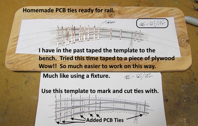


In the past I've always taped a turnout/crossing template to the top of the workbench surface. Never again. It was always a pain having it in a fixed position and awkward to solder to the PCB ties if they were on the opposite side of the turnout from where you were sitting. I cut a piece of scrap plywood I had into a rectangular shape and rounded the corners with the saw and a belt sander. Also sanded the surface with the belt sander. That all took about 10 minutes but wow, how much easier it is to now to move the turnout around for soldering. Time spent was well worth it. Highly recommend doing this if you have been taping your templates down into a fixed position.
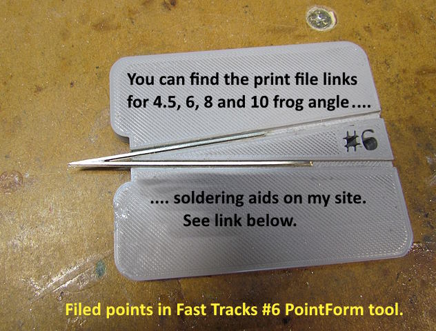
 

More info on the frog soldering jigs along with print file links ( HERE ).

The frog needed for this was a #6 so I could use my Fast Tracks #6 PointForm tool to file the frog points in a minute or so. On the next page you will see how I was also able to use it for a #10 or about any other frog angle.
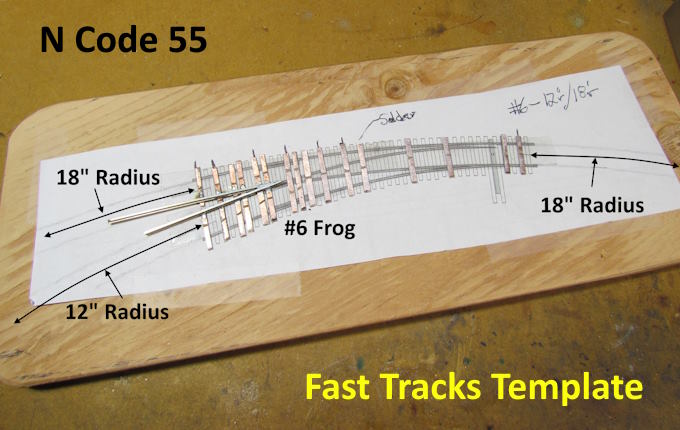
 

I always start with the frog and work out from there as it is the heart of the turnout.
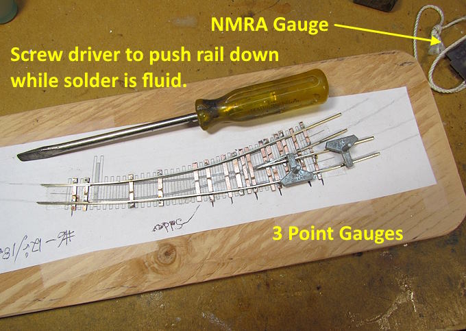
 

As I solder and as the solder joint is still fluid I'll push the rail down onto the tie with the screwdriver. If you stay on the solder joint too long the copper can lift off the tie. If I don't get the screwdriver quickly let the joint cool.....pick up the screw driver..........reheat the joint..........push it down.

The 3 point gauges speed things up and wish I would of gotten some sooner.
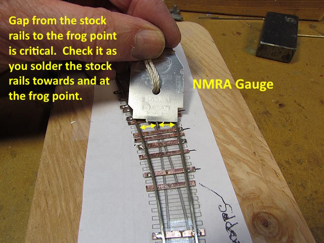
 

The 3 point gauges usually get the track into gauge but I always check it many places with a NMRA gauge. One of the most critical places to check is from the end of the frog point out to the stock rails on both sides. I'll get the stock rails held in place with a couple solder joints before and after the frog but then make sure it is right at the frog point before soldering the stock rails to more ties. This is probably one of the two main places where cars/engines have difficulty going through a turnout if it isn't right.

I leave a number of the turnout ties unsoldered until the very end just in case I need to move a rail in or out a touch.
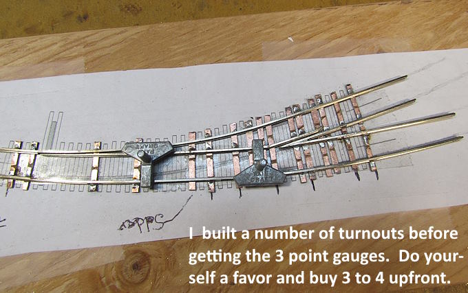


.
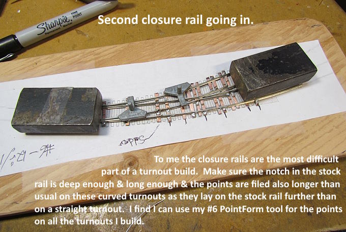
 

For me the closure rails in the middle can be the hardest part of the turnout build. I try and take my time with them and again I don't solder them to every tie until I'm certain that everything is in 'gauge'.
 

I use Superior #30 liquid solder flux on all my soldering jobs and love it. Have it in a small bottle with the tip squeezed almost shut so I can control how much I put on. At the point I use the flux....a hot iron....and I'm on/off the solder joint as soon as the solder flows (less than a second). I wash the turnout in hot dish detergent water when done

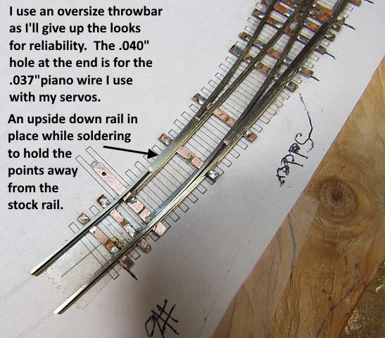
I'm a 'function' over 'looks' person so give up a little looks when it comes to the throwbar.
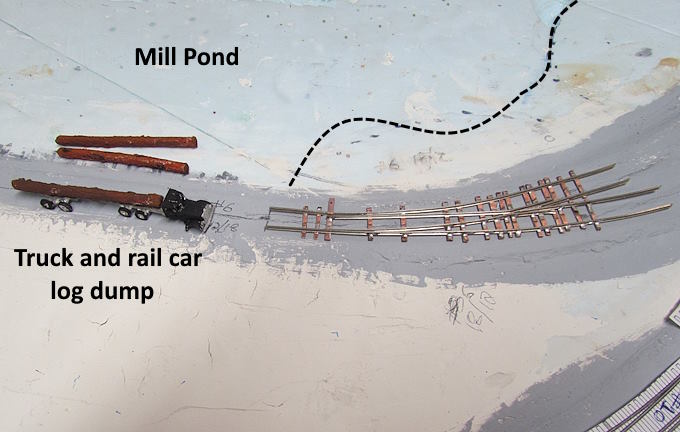
 

This turnout is just to the right of the log dump and provides a siding to move the log cars onto so that they aren't blocking the main while unloading them. The track/ties here will be filled in to the rail tops so that trucks bringing logs to the mill can also be unloaded here.
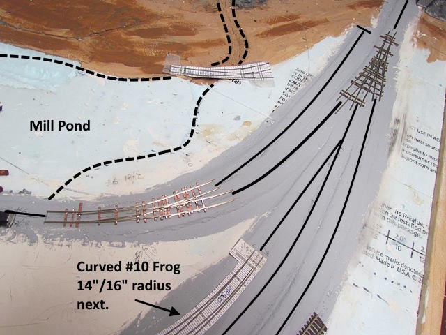
 

Next up is one more curved turnout for this side of the sawmill tracks and then three more for the other side.

To be continued and a link to this whole build ( HERE ) .

Sumner
Working in N Scale ---Modeling UP from late 40's to early 70's very loosely......

Under$8.00 Servo turnout Control --- 3D Printed Model RR Objects -- My Home Page

http://1fatgmc.com/RailRoad/RR Main/Link Page Menu.html

Sumner

  • Crew
  • *
  • Posts: 847
  • Gender: Male
  • Respect: +2411
    • My Home Pages....
Re: UP's N Scale Canyon Division Layout Build....
« Reply #128 on: November 25, 2025, 11:32:38 AM »
+4
Sawmill Curved Turnouts -- Pt. 2 & Build Tips...

The last turnout needed for the north side of the sawmill scene. Hopefully a few tips that will help you if you haven't made a turnout with a template or have.


.


I only have the one Fast Track PointForm tool but have been able to use it for every turnout/crossing I've made. Not quite as handy as having the the correct one for the frog angle you need but works, kind-of. I'll use it quickly to file to the #6 angle then loosen the fixture and slide the rail out a bit and carefully file it down to close to a #10 angle in this case. Take it out and check in the soldering aid fixture and adjust as needed. Probably spent about 5 minutes on the two rails need for this frog and then proceeded to solder them together.


As usual for about everything I solder I have my 60 watt iron set to as hot as it goes. Use a liquid flux that flows down into the joint or under a tie if that is what I'm soldering and get on and off the solder joint as soon as the .6mm solder flows into the joint. Using a lower heat means the heat travels further before the solder melts and that can cause damage at times.

Soldering to PCB ties, heat on for too long can lift the copper foil off the center of the PCB, soldering track joiners, heat for too long can melt the plastic ties and the same with components when soldering an electronics project.


Soldering iron I'm using now that works great and it is easy cheap to get extra tips ( HERE ) .


.


Measure often, especially in the area by the frog and points.


I started building turnouts and cutting isolation gaps in the rails with an OK saw that only have one tensioning position, top left on the image above. It was hard to get the blade tensioned as tight as it should be and I had blade breakage and it was harder and took longer to make the cuts. I then got the saw above ( HERE )  and after tightening the top back tension you can hone in on a good tension with the wing nut on the lower front. Blades don't break as often and cuts are finished much sooner. I use to dread doing the cuts. Now in a few minutes I'm done.

Also the vise is vital ( HERE )  along with quality blades ( HERE ) .


Next up is three more curved turnouts for the south side of the sawmill tracks. Then turnout testing and installing along with the ME code 55 flex track.

To be continued and a link to this whole build ( HERE ) .

Sumner
Working in N Scale ---Modeling UP from late 40's to early 70's very loosely......

Under$8.00 Servo turnout Control --- 3D Printed Model RR Objects -- My Home Page

http://1fatgmc.com/RailRoad/RR Main/Link Page Menu.html

Sumner

  • Crew
  • *
  • Posts: 847
  • Gender: Male
  • Respect: +2411
    • My Home Pages....
Re: UP's N Scale Canyon Division Layout Build....
« Reply #129 on: November 30, 2025, 05:10:07 PM »
+2
Sawmill Curved Turnouts -- Pt. 3 & Build Tips....

Three more curved turnouts were needed for the sawmill complex tracks & main. Below is mainly more turnout build techniques that I use. These have changed over the years and will probably continue to change. The more you build turnouts the more you find ways to improve on them.


Above is one way to use a Fast Tracks tool to make the frog points for frog point numbers other than what it was designed for. The correct one would be a little faster but filing like above only adds a couple minutes to how long it would take to file the frog points for the turnout the PointForm tool is designed for.


Using a soldering jig is also beneficial but not a necessity.


Getting the frog rails where they should be on the template is important as the rest of the turnout is built off of them. Use the template for the stock and closure rails initial positioning but using a NMRA gauge to position them by the frog is more important than where you might place them using the template only as a guide.


Above you can see the stock rails are filed a little deeper than what you might be able to do using the StockAid filing jig alone. You might also find you need to file further towards the frog for the outside stock rail of a curved turnout. The closure (points) rail lays on the stock rail for a greater distance than for a straight turnout.


I've used different things (PCB ties) to space the closure rail points out away from the stock rails to solder them to the throwbar. They worked but now found the easiest is to take pieces of rail and turn them upside down..... slide them towards the points for the gap you want...solder the points to the throwbar.....remove the pieces of rail.

I use Superior #30 liquid flux in a bottle with the metal tip squeezed shut. Put a small drop where the point lays on the throwbar. Then have my 60 watt iron as hot as it goes.....touch the tip to the joint in the flux.... melt solder into the joint and get off as soon as I see it flow and attach to both. Usually only a second or so. You don't want solder to flow to the other side of the point making it hard for the throwbar to slide under the stock rail. If any ends up on that side file it off with a thin file.


The #10 curved turnouts above are the same with one being a 'right hand' and the other a 'left hand'. They provide a cross over between the inner and outer main tracks.


The #10 lefthand above with a 14" inner radius connects the inner main track to the tracks by the sawmill.


The 3 new turnouts provide a way to enter or exit the sawmill tracks to either the inner or outer main tracks.


I like to test all my crossings or turnouts before adding the wood ties or installing them on the layout. At this point it is still easy to heat solder to melting and move rails just a bit if needed. I made the test setup above to sit on top of my test layout when needed The tracks used with it can connect to either a DC or DCC output from the DCC-EX command station or a Tech II DC throttle with power jacks.

The metal clamps can be moved or rotated to hold the crossing or turnout in place while powered tracks are connected using joiners soldered only to the track pieces. You can have a turnout or crossing in/on the tester in a minute or so.


More info and images on the turnout tester ( HERE ).

I usually test with all 3 of the locos shown above. Usually the 6 axle E9 is the one that tests the functionality of the turnout the most but the U50 with the inside sets of axles also finds turnouts that need more work.

I moved one of the guard rails and a closure rail by the frog on one a bit. Another had a short in one small section of the turnout that I miss when I checked it with the multimeter on the bench. Both were easy fixes at this point.

To be continued and a link to this whole build ( HERE ) .

Sumner
« Last Edit: November 30, 2025, 05:21:25 PM by Sumner »
Working in N Scale ---Modeling UP from late 40's to early 70's very loosely......

Under$8.00 Servo turnout Control --- 3D Printed Model RR Objects -- My Home Page

http://1fatgmc.com/RailRoad/RR Main/Link Page Menu.html

Sumner

  • Crew
  • *
  • Posts: 847
  • Gender: Male
  • Respect: +2411
    • My Home Pages....
Re: UP's N Scale Canyon Division Layout Build....
« Reply #130 on: December 16, 2025, 02:29:19 PM »
+1
Sawmill Turnout Install -- Pt. 1...

I still have one long stretch of sculptured foam scenery that needs Spackling and paint. I decided to put that off a bit and try and get the track in at the sawmill scene and also finish some other aspects of the scene.


Having finished making the turnouts and a crossing for this area the next step was to get all the turnouts in place with some push pins to get a final look at what the track plan would look like (above). Next they would be removed and then tested on my turnout tester. Follow that up with placing ties on them and then installing the servos along with caulking the flex track down to tie all the track and turnouts together for the scene above.


There are two 3-way turnouts in the sawmill's yard and instead of installing them separately I decided to solder them together as on. The rails where they would be joined were cut as a staggered cut to make the union span over a couple long ties that join them. That was done as shown above.


Normally I let the caulked down flex track to the turnouts anchor them down and leave the turnouts to 'float'. Then if they need work it is fairly easy to remove them if the work is major or they are to be replaced. Eventually if I get that far and they have been performing OK they might get ballast.

Some of the turnouts and the crossing will be connected to other turnouts and I wanted a way to then anchor them down but still be removable. To do that I'm making PCB ties with a hole in them sized so a M2 screw can be used to hold them in place (see above and following images).


Of note is that this track-work is at 57 inches on the upper level and most people are looking across it not down on it. Considering that I'll live with 'maybe' someone ever noticing the screw heads and will trade that for being able to remove any turnouts/crossings if needed. I'm well along in life at this point and find it is easier and easier to compromise on what I think is acceptable in regards to 'quality' vs. functionality.


The crossing has 4 ties with holes in them and I might only need to use three of them.


On the track coming out of the tunnel on the right side/north side there is a 3-w with a short piece of track leading into a #6 RH turnout. I modified a short piece of ME code 55 flex there to also have two ties that I can screw down. This will anchor one end of the 3-way and one end of the #6 RH turnout. Next up was testing the turnouts before adding ties and wiring to them and that was covered on the previous page.

To be continued and a link to this whole build ( HERE ).

Sumner
Working in N Scale ---Modeling UP from late 40's to early 70's very loosely......

Under$8.00 Servo turnout Control --- 3D Printed Model RR Objects -- My Home Page

http://1fatgmc.com/RailRoad/RR Main/Link Page Menu.html

Sumner

  • Crew
  • *
  • Posts: 847
  • Gender: Male
  • Respect: +2411
    • My Home Pages....
Re: UP's N Scale Canyon Division Layout Build....
« Reply #131 on: December 18, 2025, 12:33:41 PM »
+2
Sawmill Turnout Install -- Pt. 2....

There are 15 turnouts and a crossing in the sawmill scene. I debated with myself on how to control them. I ended up going with servo control like what I've used on the layout to this point. The total cost per turnout for the servo, servo bracket, servo controller and a switch box to control all of that is less than $10 per turnout and works well. You can easily adjust the throw of the points so as to not overpower them against the stock rails and you don't need a computer or any other hardware. There is some soldering to build the switch box and to modify the servo controller but all of that is easy to do and fast work. More about this turnout control option ( HERE ).

Up to this point the switch boxes to control the servo at the turnout have been located by the turnout they control. That was an option here but decided to try making a control panel and move the toggle switch, button switch and LED's to the control panel. We will see if this is a good move or not.

I started....


..... by drawing a sketch of the track plan to close-to the size I wanted the final panel to be. I scanned what I had drawn with the printer and saved it as a .jpg file. I then opened the free version of Fusion I use and inserted that image onto one of the work planes (top part of image above). Next I calibrated it to true size using the 5 inch scale that had been made on the drawing.

Next a component that would end up being the 3D printed panel top was made to the same size as the inserted image and extruded to .075" thick. Then used the image as a guide on top of the panel to create the track plan routes with line commands. They were then extruded up .125" higher than the panel's top surface (bottom part of image above). This all went pretty quick.


For printing purposes the control panel was created as 4 pieces. The top is two pieces and the holes were added for the toggle and button switches and for the LED's. It is designed to print flat on a filament print with the track plan up. The bottom was also designed as two pieces and has a top, sides and mounting tabs and is printed upside down like shown above on the build plate of the printer. This was a simple project to do in Fusion.


As mentioned above the panel had to be split up to fit on the build plate of the BamBu A1 which is 10"x10". The parts were designed to have overlay which helps with the strength along with the mounting tabs on the bottom. It could of been designed to work with the build plate on the resin printer but for a panel like this I feel the filament print is the better choice, stronger print and less likely to warp (love both types of printers though).


After adding hinges the next step will to be to wire this and there will be a lot of wires. With the control system I'm using for the servos you through the toggle.....the LED's will show the new route......push and hold the button switch....... the turnout throws.......release the button switch and the LED's stay lit but the servo is un-powered. I like this as you don't have power going to all the servos all the time and they hold position. Only the servo/servos that is being activated by the button switch is powered.

There will be a couple instances where throwing one turnout will also throw a complimentary one at the same time (cross-over situation and one route through the crossing). In those case the button switch and toggle will control two servos at the same like like what you see here........


.


There are also 4 tracks where the power can be turned on/off. A loco/train can be parked on any of these and the power turned off.


Next up will be mounting the control panel with hinges as shown above and see if it is going to work as planned in that location. Then comes the wiring.

Also wiring turnouts and the crossing at the moment along with adding ties to them, the one job I like least.

To be continued and a link to this whole build ( HERE ) .

Sumner
Working in N Scale ---Modeling UP from late 40's to early 70's very loosely......

Under$8.00 Servo turnout Control --- 3D Printed Model RR Objects -- My Home Page

http://1fatgmc.com/RailRoad/RR Main/Link Page Menu.html

Cory Rothlisberger

  • Crew
  • *
  • Posts: 306
  • Respect: +726
Re: UP's N Scale Canyon Division Layout Build....
« Reply #132 on: December 18, 2025, 12:43:32 PM »
0
That overlap between the 2 halves is very clever!

chessie system fan

  • Crew
  • *
  • Posts: 1485
  • Gender: Male
  • Respect: +1298
Re: UP's N Scale Canyon Division Layout Build....
« Reply #133 on: December 18, 2025, 11:02:11 PM »
0
I'm amazed at how fast of a modeler you are.  And then I think about my speed...  :scared:
Aaron Bearden

Sumner

  • Crew
  • *
  • Posts: 847
  • Gender: Male
  • Respect: +2411
    • My Home Pages....
Re: UP's N Scale Canyon Division Layout Build....
« Reply #134 on: December 21, 2025, 10:29:58 AM »
+2
Sawmill Turnout Install -- Pt. 2.....continued..


Trim was added to hid the gap between the 1/2" plywood under the foam board and the 1x2 fascia above it. Also it was better to screw the hinges into this new fascia vs. the end grain of the 1/2" plywood. The trim is 1/4" plywood left over from building the camper where it was used for the interior walls.


The trim will end up going around the upper level in this area.


On the lower level I have a track bus and a 5v bus that are out on the fascia. I love the fact that I don't hardly ever have to go under the layout to wire the track drops to the bus. I solder the drops to the rails. Drop them under the layout.....reach under... pull them to the side.... and solder them to the buss ( HERE ). Works great especially at my age.

I'll be soldering all the track drops at the side of the layout. One, for convenience (not having to solder looking up) and because I can't get under it with the staging area there. There will be two solder pad panels that the track drops can be soldered. One on each side of the fascia by the sawmill complex. One set of solder pads (right side) will be for the drops off the main line which I will be able to switch between DCC and DC at any time with my throttle. The three sets of solder pads to the left will be for the sawmill track/turnout drops.

The solder pads will go to two different power districts on the DCC-EX command station that will have 8 districts total, throttle switchable between DCC, DCC Program and DC. I'll probably run the sawmill tracks at DCC most all the time. The main will be switched back an forth between DC and DCC depending on which type loco is running on it at the time.


The solder pads were cut from a small sheet of PCB that was very inexpensive on eBay. The panel was designed with Fusion in and hour or so and printed with the Bambu A1 in less than 2 hours. This is one of two that will be used. One on each side of the sawmill scene to keep the track drops short. The layout is 6 feet wide here.


Another panel will go on the other side about 6 feet away.


The panel above will handle the track drops on this side of the scene.

To be continued and a link to this whole build ( HERE ).

Sumner
Working in N Scale ---Modeling UP from late 40's to early 70's very loosely......

Under$8.00 Servo turnout Control --- 3D Printed Model RR Objects -- My Home Page

http://1fatgmc.com/RailRoad/RR Main/Link Page Menu.html