I picked up a A-B-A set of the Walthers C-Liners a couple of weeks ago. While I do have the earlier Life-Like C-Liners, I wanted to see if I could do a LokSound DCC install with no cutting of the frame. MRC made sound decoders specifically for the Walthers release of the C-Liners, but I decided to skip them because a) they are apparently discontinued, and b) they're terrible. I'm happy to report Mission Accomplished!
If you want the DCC-ready C-Liners, look for the gray "Proto by Walthers" box. There is no external difference between the L-L and Walthers releases of the C-Liners besides the liveries and road numbers, so the best way to tell what you have is to remove the shell.

For this install, I used a ESU 73800 LokSound Select Micro decoder. I test-fit a v4.0 LS Micro decoder and it appeared to work with no shell or frame modifications. I will update on the final results in a future update. This installation should also work for non-sound, wire-in DCC decoders.
You can still do a LokSound DCC install in the earlier L-L, DCC-unfriendly C-Liners. The Kootenay Division blog wrote an excellent how-to. Be warned- you will need to cut into the frames.
https://kootenaymodelrailway.wordpress.com/2017/10/19/esu-loksound-dcc-sound-installation-in-a-life-like-c-liner/The
victim recipient, New York Central CFA-16-44 #6604. The NYC Cigar Band livery is the only one unique to the Walthers run, according to Trovestar. The others are undecorated and reruns of Pennsy and Milwaukee Road.

The factory DCC-ready frames will look like this in the A-units. The B-unit frames are identical except for not having a light PCB.

The first thing to do once the shell is off is to remove the motor PCB and light PCB. They both pull out towards the front. If they feel stuck, try loosening the frame halves. Now is a good time to lubricate the innards and paint the bottom of the frame black. Here are the PCBs out of the frame.

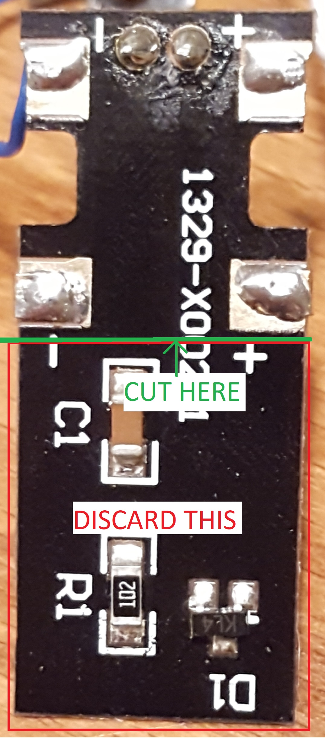
Next, you're going to desolder the light PCB from the motor PCB (I saved the light PCB, more on that later), then cut off the PCB board from behind the motor contacts. The rear portion can be discarded. I used a Dremel tool with a cutoff wheel for plastics. Wear eye protection and a respirator, you don't want the dust in your eyes and lungs!
Then, you'll need to cut the traces going from the track pickups to the motor contacts. The traces are on the top of the PCB. I cut them with an Xacto knife. Apologies for the potato photo, but the traces are more visible with flash on. I used a multimeter to test continuity. Make sure there is no continuity between the motor and track pickup.

Now you can begin soldering. The black wire goes to the left (fireman's-side) front solder pad, the gray wire goes to the left rear solder pad, the red wire goes to the right (engineer's-side) front pad, and the orange wire goes to the right rear solder pad. The track and motor wire runs from the LokSound decoder to the PCB will be very short. Note in the installed pictures, the track pickup solder pads stick out a little to the front. I soldered the track wires there so they don't get pinched in the frame slots. Once the decoder is wired up, put a piece of Kapton tape on the motor contact pads to isolate them from the decoder. The wired end of the LokSound decoder will rest on top of the PCB, while the end with all the tall capacitors, etc. on top will be nestled in the PCB trough. I offset the decoder to the left for best clearance.


At this point I suggest testing the decoder to make sure the motor functions properly. Check the motor tabs to see they're touching the brush contacts. Be careful when installing the PCB! You can bend or even break off the motor tabs if they get caught on the sides of the brush contacts. Ask me how I know...
It's moving? Sweet! Tape down the decoder, and if you're installing a non-sound decoder in a B-unit, you're done!
Next up is the lighting. I like the way the stock LED looks and the NYC ran their 4-axle C-Liners with one headlight only, so I decided to reuse the stock light. There's plenty of space in both the front and rear for SMD LEDs if you prefer to go that route, or plan to add Mars/Gyra/backup/neon underglow/etc. When reusing the stock light PCB, desolder the factory wires, and add a resistor (I used 1k ohm 1/8W) to the negative side. Do NOT reuse the factory light soldering pads on the motor PCB! Run the wires directly from the decoder to the light board. The factory wiring colors are the opposite of the NMRA standard, so you will need to swap the blue and white wires around. Walthers provided neat little channels in the sides of the frames to route the lighting wires. I used Tamiya masking tape to keep them in place and some shrink wrap tubing to insulate the white wire/resistor joint.
Time to test again. If the LED works, and this is a non-sound install, that's it! For sound, the final step is to add the speaker. I used the ESU 50321 15mm x 11mm Cube Speaker. There's enough space in the cab to use the speaker, short chamber, and end cap. You'll need to move the speaker as far back as you can and center it on the frame. You will also need to solder the speaker wires to the sides of the spring contacts to maintain vertical clearance. There's even more space in the B-unit for a larger speaker or two smaller ones. However, I found the setup I used to be plenty loud for my purposes. I used double-sided tape to hold the speaker in place for now. I will use Walthers Goo or some other adhesive later.
A look at the almost-final install before placing the shell back on. After some programming, #6604 is ready for service and waiting for sisters A #6601 and B #6900 to be outshopped!

Why "almost-final?" There's one more thing I'd like to do, and that's install keep-alive caps. There's not much space left in the front of the locomotive with the speaker in the way. I might be able to mount them above the rear worm gear in the pocket you see at the rear of the engine. Stay tuned!


