Author Topic: New brass EP-2 clinic- part 2  (Read 46306 times)

0 Members and 1 Guest are viewing this topic.

u18b

  • Crew
  • *
  • Posts: 3501
  • Respect: +1766
    • My website
New brass EP-2 clinic- part 2
« on: May 27, 2015, 09:56:33 PM »
+2
INTRO

Well, it has been about 8 months since the last post on the other thread.  So this thread could be seen as a continuation of that thread.
I think I was emotionally tired and needed a break after working on that first EP-2 for about a whole year.

But I am motivated to get back to work and have started on two more.

I'm starting a new modeling thread here because the old one was kind-of huge.
At 834 posts over 56 pages with over 1,000 photos..... it would be pretty daunting for a person who was new to this for the first time to read all that from scratch.  So it is time for a new thread.

However, I would recommend that old thread (huge though it was) because it had many fascinating turns, techniques and modeling information.  There is probably something for everybody lurking in there.   I tried to write that thread from the outset to show exactly how I did what I did, why I did it, thought processes and problems.  And what made it even better for me was the wonderful help I received from this board.  Ideas from this board made it into that final model.

Here is the old thread
https://www.therailwire.net/forum/index.php?topic=31042.0


Now on this new thread, I will NOT be posting the same exact procedures.
I may summarize a few points with only a few shots and then focus the larger number of shots and explanations on what I am doing new.

I'll make a few posts to get us started.  They will be orienting in nature.
« Last Edit: May 15, 2023, 07:56:36 PM by u18b »
Ron Bearden
CSX N scale Archivist
http://u18b.com

"All get what they want-- not all like what they get."  Aslan the Lion in the Chronicles of Narnia by C.S.Lewis.

u18b

  • Crew
  • *
  • Posts: 3501
  • Respect: +1766
    • My website
Re: New brass EP-2 clinic- part 2
« Reply #1 on: May 27, 2015, 09:57:29 PM »
0
ORIENTING POST


In the early 80's, NJ Custom Brass commissioned Kumata in Japan (also called KMT) to make a brass model of the Milwaukee Road EP-2 class bipolar electric locomotive.  The model was released to the N American market in September 1983.

The end result was mixed.  Overall the model was impressive at the time.  It was also very expensive (possibly the most expensive N scale loco made until that time).  The reason was that Kumata considered this not one, but two locomotives drawbared together.  And actually, it was.   Each Cab had its own motor and pickup and this model was “2 locomotives.”

But they ran poorly (if they ran much at all).  There were also some detailing deficiencies/compromises.  Furthermore, for the modeler, that early model most accurately captured the look of the prototype around 1920- one year after delivery.  So if you wanted to model the Hiawatha era, the model was “in the neighborhood”, but not exactly right.

Here is the old NJCB original EP-2.  Notice:  there are no sand boxes on the noses, a tall boiler room door on one side, and an overall lack of detail on the roofs.  And out of 14 axles, only FOUR were powered.


Then, in 2003, Kumata created an all-new EP-2 in brass in N scale, which until recently was unknown outside of Japan.  This new model had more accurate details appropriate for the Hiawatha era and ran much much better. For example, the shells had an A (clean roof) and a B end (busy roof), operating headlights, MUCH greater detail, and 4 axle power trucks now had all FOUR axles powered insteasd of 2.

Kumata made 50 of these in three versions.  35 were ready to run painted in three schemes (15 or 16 each.  15 existed in kit form (5 each version).   34 ready to run painted locos and 5 kits were sold in Japan.   Kumata planned to export them to the USA, but the exchange rate was not favorable – so they sat on shelves for years, gathering dust in Japan. 


And here are the three versions of the new 2003 EP-2.
I have no idea yet what the RTR painted units sold in Japan looked like nor their somewhat cryptic names.  The labels say “Black Painting”,   “Hiawatha Painting”,   and  “ Milwaukee Painting”.

I have just simply called them by the names and versions that make sense to me.

The first version which appears earlier since it has no horn is good model of the late black scheme- numbered in the E series.
But this version could also be used for other schemes.


prototype   http://morphotoarchive.org/rvndb/rvn-jpgs/RVN09773.jpg


The second version appears more unique since it is the only one that has NO sand boxes on the nose.
The 5 prototype EP-2s were purchased new Dec 1919- 1920 and had internal sand hatches and lines that clogged.  Around 1921 or 22, they started making modifications which included sand boxes on the nose.   Thus, after 1922 up to the infamous/disastrous 1953 rebuild, there is only ONE moment that any of these 5 locos had no sand boxes.  And that was in 1948.  And the second version of the brass model is almost absolutely perfect for this locomotive.

Milwaukee Road exhibited the brand new Hiawatha at the 1948-1949 Chicago Railroad Fair with a brand new scheme- commonly called the Railroad Fair scheme.  They removed the boiler from the boiler room (filling it with batteries for self propulsion) and they removed the sand boxes (presumably to reduce weight) on E-3.  That's it.   This was the ONLY loco with no sand boxes.   So while this is an AWSOME model of this moment in time, KMT could have probably made a better marketing decision with another variation.  (actually, all the brass model needs to become something different is the addition of sand boxes- which could actually be added).

Well, the first thread was building this wonderful model as intended.  Here it is.


Overall, this is pretty accurate.  I was very pleased with the result and this is a MUCH better model because of the input of this board.  Thanks.


The third version must almost certainly date from the early 1950s.  On this version, the windows on the nose doors were welded over with sheet metal (most important dating detail).

Here it is.


This is E3 during the early 50s:   http://donsdepot.donrossgroup.net/dr1102/sk325.jpg


For this new thread, this later version is the version I'll be making.

My goal is to make a pair-- number E4 and E5.   These are identical.  I'll be making the multiple headlight version.   These two road numbers had three sub-headlights in the one casing. (some had 4).

« Last Edit: May 27, 2015, 10:05:21 PM by u18b »
Ron Bearden
CSX N scale Archivist
http://u18b.com

"All get what they want-- not all like what they get."  Aslan the Lion in the Chronicles of Narnia by C.S.Lewis.

u18b

  • Crew
  • *
  • Posts: 3501
  • Respect: +1766
    • My website
Re: New brass EP-2 clinic- part 2
« Reply #2 on: May 27, 2015, 10:01:59 PM »
0
A Backtrack-   Adventures in sound

The EP-2 brass model has two motors.  In other threads, I have commented on how this is one of the Achilles heels of multi-motor locos.  If the motors do not perform identically, they will work against each other and performance will degrade.   It is thus important to get each Cab unit running as closely as possible.  (DCC helps a LOT).

Now, since I had multiple motors to work with, the concept of motor pairing seemed important.

I test ran my motors and they did not all run the same (nor sound the same).

I could have put a volt meter and measured volts and amps to get a look into the motors.

But I did something different.

I obtained a sound app for my Iphone.   Using iAnalyzerLite (free)
https://itunes.apple.com/us/app/ianalyzer-lite/id342456044?mt=8

With this app, I measured a sound pattern for each of the motors.

The results were visually amazing.

Here are a few end results.  Study them and notice the differences.


The top squiggle line is a frequency chart.

I'm not sure what the middle and bottom patterns mean-- but the bottom resembles the output of a typical sound file on your computer.

But it doesn't matter.  We don't have to know what these MEAN....... we just need to compare them.

Look at the next one.  It looks VERY different.  This motor SOUNDS louder.... but it also LOOKS louder from this output.


And this one you can see falls in between the two extremes.


So what I ended up doing was pairing motors that had similar visual outputs.


An interesting new tool for modeling.

« Last Edit: May 27, 2015, 10:08:44 PM by u18b »
Ron Bearden
CSX N scale Archivist
http://u18b.com

"All get what they want-- not all like what they get."  Aslan the Lion in the Chronicles of Narnia by C.S.Lewis.

u18b

  • Crew
  • *
  • Posts: 3501
  • Respect: +1766
    • My website
Re: New brass EP-2 clinic- part 2
« Reply #3 on: May 27, 2015, 10:12:22 PM »
0
I might get one more post in later tonight.

The rest will flow as before.  I model in spurts.
My goal would be to try and have these two finished by the end of the summer.

(I know, I know, based on the last one, some of you are probably laughing yourself silly about now).   :ashat:

Ron Bearden
CSX N scale Archivist
http://u18b.com

"All get what they want-- not all like what they get."  Aslan the Lion in the Chronicles of Narnia by C.S.Lewis.

u18b

  • Crew
  • *
  • Posts: 3501
  • Respect: +1766
    • My website
Re: New brass EP-2 clinic- part 2
« Reply #4 on: May 27, 2015, 10:16:39 PM »
0
Here are my two targets.  These shots are posted for educational/research purposes.

You can see the watermark.  This guy sells on ebay if you want to get a clean copy for your collection.


Ron Bearden
CSX N scale Archivist
http://u18b.com

"All get what they want-- not all like what they get."  Aslan the Lion in the Chronicles of Narnia by C.S.Lewis.

u18b

  • Crew
  • *
  • Posts: 3501
  • Respect: +1766
    • My website
Re: New brass EP-2 clinic- part 2
« Reply #5 on: May 27, 2015, 11:25:30 PM »
0
I'm skipping a lot here and just summarizing.

It takes a lot of work to get the kits up and running well.
Consult the previous thread for full details.  I'm not concerned with detailing yet nor DCC.  I'm just getting them running.

But I made a couple of changes based on what I learned from the previous thread.

Here is a B Cab.


The shell is held by three screws through the walkway- as you can see.  Here is my re-designed mechanism.


Here is the wiring harness I made.


That blue part is an analog plug.   You can see the DCC coloring on the left.  Rail power is the outside colors (red and black) and the inside pins are the motor leads (orange and gray).

The blue plug pulls out (to be replaced in the future with a decoder).
The red plug at the top goes to the front truck under the motor.
The rest remains with the motor permanently.

Here is how I made an analog plug.

When red and orange and   the black and gray are paired together, you now have an analog loco.
Here you can see the jumpers.


Shrink wrap is added to cover the jumpers.


One more shrink wrap and a little superglue now makes an end that can be pulled on when removing the plug.


I also made a point to label parts.  This is motor 4.  And this goes in the B cab.


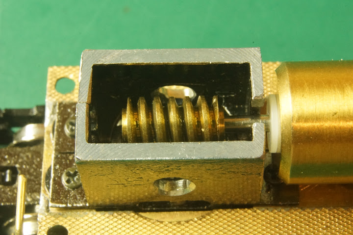
One of the most important mods I made was to cut a hole in the gearbox so that I could inspect the gear mesh with the worm.  Getting this mesh perfect is key to performance.


Another important change was to add a bit of solder between the outer walkway and the main frame.
This I discovered is a weak spot.  Those joints pop loose with handling.  Adding extra solder gives them greater strength.
Not exactly beautiful, but the shell hides it.


That photo above shows a change I made since the last thread.
You can just see MicroTrains black truck washers under the gearbox.
By raising (shimming) the gearbox up, it actually LOWERS the walkway toward the truck.
Remember, this loco appears a little too high.  I may or may not keep this later.  It depends on what happens when I add my extra frame later.


But THIS is the best and most important change I made.
You can see that I cut a slot in the right edge of the gearbox.
This allows the motor shaft to slip out of the gearbox.
Consequently, I can now remove the motor WITHOUT disassembling the gearbox (a MAJOR hassle).

I cannot tell you how much better this makes loco servicing.


Now, one of the problems I had before was that in order to access those screws between the gearbox and the flywheel, I had to shift the flywheel as far over to the motor as possible AND use a very tiny screwdriver to get at the screws.  But this made oiling the inner motor bearing a challenge.

But now, with that slot in the gearbox, NONE of this is a problem anymore.
I am able to move the flywheel away from the motor and cover the screws on the gearbox.
No problem-- I can just lift the motor out now.
THEN I can easily get at those screws.
Also, oiling the motor is VERY easy now.


To remove the motor, I just pull that red plug up top and remove those two screws on the back.
That is all.
Easy-peazy.  I love it.


Ron Bearden
CSX N scale Archivist
http://u18b.com

"All get what they want-- not all like what they get."  Aslan the Lion in the Chronicles of Narnia by C.S.Lewis.

victor miranda

  • Crew
  • *
  • Posts: 1604
  • Respect: +2
Re: New brass EP-2 clinic- part 2
« Reply #6 on: May 28, 2015, 10:08:46 AM »
0
Hi Ron,

I am here writing because I like what you do.
I worry when I give you my thinking that is may not be taken well.

the second thing I thought was how many cars is he pulling?
you have very little to stop the worm from lifting off the wheel it drives when under load.
I would add something to the front of the motor to hold it down.

a front motor mount with screws from the bottom the first thing I'd consider.

.... it may not be a problem if you avoid things like traction tires.

ah, you do such pretty work.  I'll try to be quiet and watch.

u18b

  • Crew
  • *
  • Posts: 3501
  • Respect: +1766
    • My website
Re: New brass EP-2 clinic- part 2
« Reply #7 on: May 28, 2015, 10:54:30 AM »
0
Hi Ron,

I am here writing because I like what you do.
I worry when I give you my thinking that is may not be taken well.

the second thing I thought was how many cars is he pulling?
you have very little to stop the worm from lifting off the wheel it drives when under load.
I would add something to the front of the motor to hold it down.

a front motor mount with screws from the bottom the first thing I'd consider.

.... it may not be a problem if you avoid things like traction tires.

ah, you do such pretty work.  I'll try to be quiet and watch.

I enjoy comments and questions.   We all learn from each other.

You have made a great point.

What I hear you saying is......
Have zero worm bearings has two consequences.  yes, it reduces friction, but I also no longer have anything holding the motor down under load.

So when the loco is under heavy load, that twisty direction of the worm and main drive gear is going to want to LIFT the worm.  When that happens, I hear a ratcheting sound as the worm teeth lift over the drive teeth and the motor bounces up and down.

You are correct.  That is a danger.

Here are my thoughts.

1.  The EP-2 locomotive only RARELY pulled freight (there is a great old photo of a black EP-2 pulling ice reefers full of fish advertising that this train goes to the coast.).  But 99% of the time this loco pulled passenger trains.

The Olympian (heavyweight) pulled about 9-11 cars.   During the Hiawatha era when cars were also getting lighter, that number went to 11 or rarely up to 13.

The brass model can pretty much pull a prototypical train.  Railway Classics made a wonderful brass Olympian Hiawatha passenger car set- which would of course be heavy.  Not sure it could pull that whole train.   But in plastic cars, mine will pull 9 cars on (fairly)  level track with about 11 inch curves.

I have never heard a ratcheting sound.  The wheels just slip when overloaded.

2.  That is probably because I DO in fact apply a downward restraining force.

The L-angle that holds the motor.  I bend it less than 90 degrees.  So the motor is always being pressed downward toward the worm being lower.   The old shim under the motor lifts the motor to the correct height.


Ron Bearden
CSX N scale Archivist
http://u18b.com

"All get what they want-- not all like what they get."  Aslan the Lion in the Chronicles of Narnia by C.S.Lewis.

u18b

  • Crew
  • *
  • Posts: 3501
  • Respect: +1766
    • My website
Re: New brass EP-2 clinic- part 2
« Reply #8 on: May 28, 2015, 11:08:56 AM »
0
The timing of Victor's question was actually great.

Shimming the motor is kind-of a pain. 
You can see it under the front of the motor.


I began to look for other/better ways.

What about a screw?

--I could install a screw into the frame...... but the frame is not very thick.  I would not have a lot of adjustment, and the screw could be wobbly.  The screw cannot stick THROUGH the frame because the circuit board is on the underside.

What if I mounted a brass nut to the frame?  And screw the screw in there?

That seemed like a good way to go.  But how?

00-90 is so tiny, would be the same as a screw in the frame.

0-80?  Maybe.

1-72, 2-56?  How big would be too big?

Went to the hobby shop and bought some screws and nuts for experimentation.

(Dang, those things are expensive!)

1-72 nut on the frame was too tall with the screw- so 2-56 was also out.
So 0-80 mounted to frame might work with a flat-head 0-80 screw.

Disassembled the loco down to the frame......................

.......... and the heavens parted! ..........  (lilting music is playing).


There are two large holes in the frame.  One is for the truck retaining screw.  The other is just a pass-thru for the jumper wire.

A 1-72 nut fit almost PERFECTLY into the pass-thru hole.

Ron Bearden
CSX N scale Archivist
http://u18b.com

"All get what they want-- not all like what they get."  Aslan the Lion in the Chronicles of Narnia by C.S.Lewis.

u18b

  • Crew
  • *
  • Posts: 3501
  • Respect: +1766
    • My website
Re: New brass EP-2 clinic- part 2
« Reply #9 on: May 28, 2015, 11:18:54 AM »
0
The nut is just barely too tight to seat with your fingers.  So a little gentle tapping gets it into place.


Trial and error tapping gets it about even with the bottom side of the frame.


Any long 1-72 screw can now be pulled to line up the nut perfectly.


Now to make the nut permanent.  I tried solder, but was unsuccessful.   There is just too much of a heat sink happening.  A resistance soldering station would have gotten it- but I don't have one (yet).

So i VERY carefully applied superglue around the outside edges of the nut.


And the top side.


When dry, file it all smooth on the underside where the circuit board goes.


Ron Bearden
CSX N scale Archivist
http://u18b.com

"All get what they want-- not all like what they get."  Aslan the Lion in the Chronicles of Narnia by C.S.Lewis.

u18b

  • Crew
  • *
  • Posts: 3501
  • Respect: +1766
    • My website
Re: New brass EP-2 clinic- part 2
« Reply #10 on: May 28, 2015, 11:34:42 AM »
0
Nice and smooth now.


Walthers sells a Nylon 1-72 screw.  I used an Xacto knife to flatten the head.


Of course the screw is too long.


So rail nippers cut it off


And a file smooths it down.


THAT is pretty close to what I had before.


But wait!  I just stopped up my pass-thru hole for the circuit board wire.
I need a new hole.

That spot is right below where the wire runs up to the motor.


Used a bigger drill bit to slightly taper the hole so the edges were not so sharp.


Starting reassembly.


NOW we're talking. 
This is so much better.  No more shimming.  Simply make adjustments to the screw to change the height of the worm.


In fact.... surprise.  It is better than I thought.
Since the screw is slotted (not phillips head) I can access the slot with a tiny screwdriver from the side.
So I can make adjustments without disassembly.


I love it when a plan comes together.

Ron Bearden
CSX N scale Archivist
http://u18b.com

"All get what they want-- not all like what they get."  Aslan the Lion in the Chronicles of Narnia by C.S.Lewis.

u18b

  • Crew
  • *
  • Posts: 3501
  • Respect: +1766
    • My website
Re: New brass EP-2 clinic- part 2
« Reply #11 on: May 28, 2015, 11:51:55 AM »
0
Victor,

With these new photos, I'm able to draw out the forces I'm applying.


The motor mount L-bracket places a downward force (red) and the screw lift up the motor (blue).

So the motor is held pretty firmly.  even with no bearings.
Ron Bearden
CSX N scale Archivist
http://u18b.com

"All get what they want-- not all like what they get."  Aslan the Lion in the Chronicles of Narnia by C.S.Lewis.

victor miranda

  • Crew
  • *
  • Posts: 1604
  • Respect: +2
Re: New brass EP-2 clinic- part 2
« Reply #12 on: May 28, 2015, 12:08:15 PM »
0
a pre-load works.

I like your solution.

victor

Cajonpassfan

  • Crew
  • *
  • Posts: 5371
  • Respect: +1953
Re: New brass EP-2 clinic- part 2
« Reply #13 on: May 28, 2015, 09:05:42 PM »
0
All *that* work to do *that*! Clever. And Victor is right on; it is pretty :D
Otto K.

u18b

  • Crew
  • *
  • Posts: 3501
  • Respect: +1766
    • My website
Re: New brass EP-2 clinic- part 2
« Reply #14 on: May 29, 2015, 11:12:08 AM »
0
All *that* work to do *that*! Clever. And Victor is right on; it is pretty :D
Otto K.

Actually, it took more time to photograph it than doing it.
This step moved pretty quickly.

Did the other three last night.

Next step is to design a custom weight.
Ron Bearden
CSX N scale Archivist
http://u18b.com

"All get what they want-- not all like what they get."  Aslan the Lion in the Chronicles of Narnia by C.S.Lewis.