Given that description I'd say you have it made. Since you can apparently only run one train at a time I'd keep it as simple as possible. Use the heaviest bus wire you can reasonably find, to avoid voltage losses, and make sure you have plenty of track feeders. If you ever do switch to DCC, you'll be thankful for the current capacity. There's no need for two cabs if you can only run one train.
For the spurs? sidings? I wouldn't bother with power routing turnouts, although powered frogs are nice. I would put gaps or insulated joiners on the siding end and power the track through an on-off toggle. That way you can easily store an engine there if you like.
If you do use power routing turnouts, you'll still have to gap the mainline to prevent shorts, but that won't require any extra wiring.
Back in the horse and buggy days, when I was running DC to power my portable layout (

), I powered/de-powered my sidings using the DPDT switch on my Tortoises underneath actuating my hand-laid turnouts' throwbars. That worked pretty good. If I wanted to park more than one engine or train on a siding (depending on its length) I'd divide the siding up into two sections, with some sort of indicator (like a telegraph pole with stripes painted around it like UP does) to indicate where the gap was. If I wanted to divide it up into more sections to park more engines, I'd use a toggle switch for each additional section.
My "rule" is to power each and every section of rail using feeders, either fed directly from the bus (thanks Peteski) or fed routed power from a switch of some sort. Since I build my own turnouts, the only "power routing" turnouts I'm familiar with are Pecos which are on my friend Nate's layout and use the closure points to route power. We're always fiddling with them however and I don't consider them to be "reliable", but for Nate, they're simple and work most of the time with just a flick of the finger.
I have mixed opinions about live frogs. I've got several #6's on my layout which I laid, then cut the gaps on either end of the frog where the prototype would have rail joiners...in other words, really close to the wing rails and point of the frog. I've experimented with hand-laid #7's also, but I don't have any #7's on my layout. My experience with the dead-frog #6's is that every engine I have runs just fine through the short dead frog on my #6's. On my #8's (and every turnout bigger than that) some of my shorter diesels won't run through these with a dead frog...and I both construct prototypically proportioned frogs that are much shorter than anything on commercially available turnouts, and cut the frog-isolating gaps really close too. #8 frogs are just too long for N-scale NW-2's and Alco S-2's to run through unless they're powered.
As to bus wires. I found a really good deal on eBay for 12 ga. high-purity. low-ox, lotsa fine wires premium speaker wire in a black/red zip format. Like 60 bucks for a 250 foot reel. Since I have a lot of modules/sections to build, that reel works well for me and you might find something similar online in a smaller quantity for an equally good price. However, looking back on it, I could have saved a bit of money and had better signal-loss capabilities (less signal loss) with 14 ga. wire. I'm not an electrical engineer, but sometime about six months after I'd re-done my wiring to Ntrak DCC spec's, I read a treatise on one of the boards by an electrical engineer that the physical dimensions of 12 ga. encourages signal degradation much quicker (distance wise) than does 14 ga. buses being identical in every other aspect. However, 12 ga. works better for less current drop (less resistance) in a analog/DC powered layout. However, he was adamant (as were several others who know more about it than I do) that the quality of wire makes a HUGE difference. I got that message early, which is why I went with really excellent quality wire.
You might notice from the accompanying photo that NO FEEDERS run to my 12 ga. buses. I use 14ga. sub-buses to run between the main power buses and the 22ga. feeders which keeps the main power buses straight and neat, and the feeders short (as they should be...less than 6" long). The 14ga. sub-feeders are 3' long at their longest, which is a really short run for 14ga. feeders so I don't worry about signal or current loss in that distance.
Here's a photo of my DCC wiring which, with the addition of lots of toggle switches and extra wires running off my Tortoises for power routing, would be the same for DC:
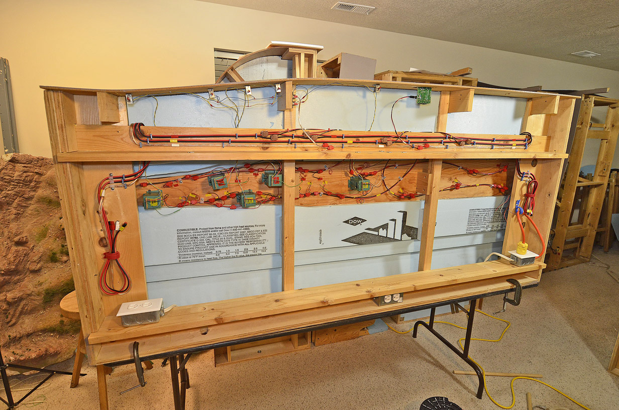
You'll see the red/black power buses that are identified by yellow or red electrical tape. You'll also see a 14 ga. clear speaker wire bus (white tape) that's the DC bus which powers the Tortoises and the Loconet Panels on the front of the layout. The wiring for the SPDT (center off) toggle switches, located on the inside of the front fascia controlling the Tortoises is left over from my 20+ year old straight DC wiring and is still sort of a "rat's nest", but nothing compared to all those wires from the old DC buses and from one side of the Tortoises integral switches used to power sidings. Missing also are all the toggle switches for facilitating travel from one mainline to another in DC as well as the power on/off toggles for a lot of the sidings which were divided up into more than two sections.
My layout is divided up into 6' sections/modules for portability's sake, so there are Anderson Powerpole connectors at each end for track power and DC power.
I also elected to use genuine 3M IDC's (Insulation Displacement Connectors) instead of solder joints this time after researching their reliability and general use. I also got hellacious good deals on both brown and red connectors in bulk on eBay...I mean like ten times cheaper than at Micro Mark or any local dealer.
I have yet to have a problem with my IDC's, whereas I have had problems with my soldered joints, and I know how to solder.
The easiest way to solder feeders to your rails is to solder them to the sides. This has several advantages, two of which are they're easy to solder and easy to locate if you ever have a problem. The main detractor is that they're ugly. I decided to solder all of my hundreds of new feeders to the underside of the foot of my rails, which makes them invisible when track is painted and ballasted...which is cosmetically GREAT, but if you need to find them, you'll have to get underneath your layout most of the time. They're also not so easy to solder, but easy enough. I started out by drilling a 1/16" hole between the ties on the outsides of the rails for each feeder, but ended up drilling a larger hole in the middle of the track between the ties to accommodate two 22 ga. insulated wires, each stripped end going to its respective rail from that single hole. That made things a bit easier, particularly on uncut 3' long sections of ME code 55 flex. No getting around it that when the rail sections get short, it's a PITA to solder every one of them with a feeder. However, it's worth it for trouble-free smooth running. I admit that in a few instances I cheated by soldering a 22 ga. wire between two sections of rail, but only in areas that it was impossible to run a regular feeder because of subroadbed risers, hidden screws or a Tortoise being in the way.
Personally, I like wiring. It's a lot like a puzzle and I get a lot of satisfaction after its all done and my trains are running flawlessly. However, troubles like phantom shorts can really be frustrating. To lessen this happening, always insert an insulative sheet of Styrene or even paper between your gaps, and check each connection progressively (as you connect them) with your ohmmeter when connecting feeders to buses so if you have a short, you'll know exactly what section of track it's coming from.
Also, some of the most impressive layouts from a railfanning aspect are layouts that have a simple trackplan and utilize N-scale's great scenery-to-track-ratio. Since your preferences are pretty well set, I think you'll do okay with the relatively simple design you've told us about.


