Author Topic: Motor behavior and driveline concepts - (a roundtable discussion?)  (Read 4952 times)

0 Members and 1 Guest are viewing this topic.

mmagliaro

  • Crew
  • *
  • Posts: 6262
  • Gender: Male
  • Respect: +1780
    • Maxcow Online
0
Folks,
I've been beavering away on remotoring an old Arnold Rapido 4-6-2 Pacific.   This was experimental in nature, and
I was asked to delve into it by a few people.  The goal was to replace the old motor with something inexpensive
and commonly available, and come up with better, smoother performance than the original.

This long-winded intro will lead to several questions I have about why the mechanism is behaving the way it is, and
more general philosophical questions about motor behavior and how to set up a driveline.  If you are interested in such matters,
read on.
If not...  next thread! ;-)

I'm hoping this opens up contribution of good opinion and knowledge on this stuff.

Here's a photo of what I have in it now:


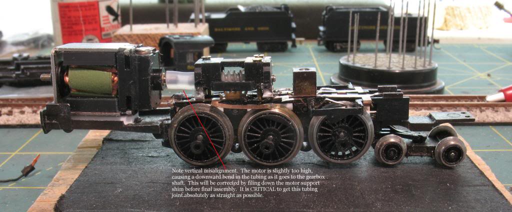
Please ignore the obvious misalignment of the rubber tube.  This photo was taken before I had the motor properly
shimmed and permanently screw-mounted to the frame.  That has long since been corrected.

The worm carrier is from a Bachmann H16-44.  It is a plastic worm, and it has plastic washers on each
end of it inside the housing.  The worm axle just rides in the plastic housing.  There are no bronze bearings.

The motor is the venerable old 1990s Lifelike diesel motor.  5-pole, skew-wound, open frame.  And if you know this motor,
you know it has the power of a bull, and pretty darn good low end performance. 

They are linked by a piece of silicon rubber aircraft fuel line tube.  It is very flexible and very grippy.

So, after carerfully adjusting the mount and watching the old ammeter, with the engine running free on
the workbench, I got the current draw at 6v down from about 75ma to
about 52ma.  And given that the motor draws 40ma when it is running free in your hand, I though that was doing
mighty good for an ancient mechanism with axle bearings, big chunky gears, and wipers on the driver tops.

After I used a Dremel to cut off the back motor shaft, doing it carefully and very slowly so that it didn't heat up,
I noticed that it didn't quite run as well.  Then I realized that one of the magnets had come loose in the motor housing
(a common problem with this LL motor)
So I repositioned and glued the magnet, and Bob's your uncle, it ran very nicely again.

I ran it overnight at 6v as a torture test.

In the morning, it had stopped.  The wheels were not stuck.  All the gears were free.
I nudged the armature, and off it went, running again.  I let it spin at a variety of voltages, and it seemed
to be running fine.

*****************************************************
Here, the round-table questions begin:
*****************************************************
1. Why did it stop? 
It wasn't running anywhere near it's "minimum" speed, meaning I had watched it on the bench
for more than an hour and it was spinning at 6v well above where it even *thinks* about stopping.

Perhaps a chunk of brush in the commutator?  Don't know.

After I got it running again, it runs, but is back to drawing around 75ma, not 50.  And at 12v, it draws about 100ma,
whereas before, it was more like 70.
In spite of this, it does not get even warm, and it just gets better and better.  It is now so smooth that it
can sustain speeds under 5 scale mph (on the bench, that is, computing it by the driver revolutions).
It couldn't do anywhere near that good a day ago. 

2. So, what's with the higher current?
Usually, motors wear in, smooth out, and the current drops.  Perhaps
the brushes and comm have worn in a little, are making better contact, the motor is making more power, but it's drawing
more current to do it?  If so, I have no problem with that.

3. What about that rubber tube drive?
I did try a NWSL cup and ball, but I could not get it to run as well as the tube, and there isn't enough room for a full
universal with dual cups.   It does occur to me, however, that the rubber tube effectively joins the
worm shaft and the motor shaft into one continuous piece, lengthwise.  Perhaps that is a drawback.
As the engine runs, and the worm pushes on the idler gear to drive the engine, the worm is thrust one way or
the other in its housing against its plastic washers, and because of the way the motor is connected,
the armature is also forced in that direction.  I don't see how that's any worse than a normal worm drive, where
the arm is pushed that way.   Is there more to this that I don't see?  Opinions.

So there it is, motor nuts and mechanism fools.    I welcome all advice, commentary, and suggestions.   Just
stencil them on the back of  a Steinway Model "O" grand piano and mail to....


« Last Edit: July 02, 2017, 03:56:24 AM by mmagliaro »

peteski

  • Crew
  • *
  • Posts: 31825
  • Gender: Male
  • Honorary Resident Curmudgeon
  • Respect: +4607
    • Coming (not so) soon...
Re: Motor behavior and driveline concepts - (a roundtable discussion?)
« Reply #1 on: February 07, 2013, 01:35:24 AM »
0
No comments so far - just a question: When you found the motor stopped (with 6V still applied to its terminals) did you check if the motor (armature) was warm or cold?  If it was cold then there there was an open circuit somewhere (commutator?)  While I haven't tested it, I suspect that with 6 volts constantly applied to a jammed armature, the windings to which the power was applied to would have been quite warm.
. . . 42 . . .

Chris333

  • Crew
  • *
  • Posts: 18093
  • Respect: +5511
Re: Motor behavior and driveline concepts - (a roundtable discussion?)
« Reply #2 on: February 07, 2013, 04:08:06 AM »
0
Well I can't even figure out how to get my meter to read milliamps so I won't be much help.  :|

Lemosteam

  • Crew
  • *
  • Posts: 5752
  • Gender: Male
  • PRR, The Standard Railroad of my World
  • Respect: +3154
    • Designer at Keystone Details
Re: Motor behavior and driveline concepts - (a roundtable discussion?)
« Reply #3 on: February 07, 2013, 06:34:13 AM »
0
Max, now THAT looks familiar! :D

With all my LL endeavors, I think that the donor locmotive was usually new and so probably not broken in, i.e. the brushes have not fully taken on the commutator radius due to wear. With a flat brush (not sure if these are made with a concave end out of the factory) contact is only made at a line tangent of the commutator and as the brush wears, more contact is made.

I can't imagine why it stopped.  Was the motor humming?  Maybe one of the brushes got jammed away from the commutator with a non conductive chunk of plastic creating the open circuit as peteski suggests?  When you rotated the armature the chunk came loose...

The forward and reverse motion of the worm in the gearbox you have made is known as axial thrust.  Clearance between the worm and idler gear teeth is known as sideplay.  Axial thrust is reduced by shimming between the wom and the bearing.  Sideplay is reduced by bringing the idler and worm axes closer together (if they have a perfect tooth mesh).  The more you can reduce of both, the better the mechanism reaction time will be.  Too close and friction will increase and transfer that friction in the form of radial load back to the motor, needing more torque to turn the mech.

Knowing your skills I'm sure the mesh is great, but I would shim to redcue thrust if there is a lot of axial movement.

As far as the tubular driveshaft goes, this design is very forgiving regarding ouput shaft-to-input shaft alignment.  you have a very short piece of tubing in there so the twist in the tube from startup torque should be minimal.  I don't think this is addling a lot of load to the motor.

You say the mech is getting more smooth as time goes on, maybe everything from the motor to the drivers is getting acclimated to each other in the form of wear....

I'm with Chris on the electrical side, as Shulz would say "I know nothing!!"

johnh35

  • Crew
  • *
  • Posts: 255
  • Respect: +1
Re: Motor behavior and driveline concepts - (a roundtable discussion?)
« Reply #4 on: February 07, 2013, 09:43:40 AM »
0
Hook the positive output of the controller to the negative of the ammeter. Hook the positive of the ammeter to the track lead and make sure the meter is set to amps and not volts. That is all there is too it

randgust

  • Crew
  • *
  • Posts: 2560
  • Respect: +2039
    • Randgust N Scale Kits
Re: Motor behavior and driveline concepts - (a roundtable discussion?)
« Reply #5 on: February 07, 2013, 10:35:26 AM »
0
That sure looks like the old venerable kato PA1 motor I use in my RSD15 conversions, too.  Those are so good I glued them to the frame and I've never touched them in....20 years now.

Normally I'd say that you really don't want to put that much thrust on the motor washers via the flex coupling, but that motor may be up to it.  Most aren't.  You need a real bearing surface, or washers, on both ends of the motor up against a bronze bearing for the shaft, to take a sustained load.   Normally the worm bearing takes the beating, not the motor bearing.  But if you've got enough thrust washers on the worm, they may be taking it anyway and the thrust never hits the motor bearings in this instance.  Follow?

If you can get it adjusted and set through the coupling so that the worm bearings are taking the hit and the motor bearings aren't I think you have a winner.

Lemosteam

  • Crew
  • *
  • Posts: 5752
  • Gender: Male
  • PRR, The Standard Railroad of my World
  • Respect: +3154
    • Designer at Keystone Details
Re: Motor behavior and driveline concepts - (a roundtable discussion?)
« Reply #6 on: February 07, 2013, 11:04:10 AM »
0
That Life like motor has spherical bronse bearing molded in the plastic houlsings at each end and should be able to handle much thrust.


C855B

  • Crew
  • *
  • Posts: 10673
  • Respect: +2288
Re: Motor behavior and driveline concepts - (a roundtable discussion?)
« Reply #7 on: February 07, 2013, 12:01:35 PM »
0
I'd send you that piano, Max, but I can't seem to find the keys. :trollface:

I know this is a "merely obvious", but do you get the same "new" current draw backwards and forwards? I think the mention of thrust induced by the worm might be a factor. I noticed that the piece of tubing is awfully close to the worm carrier, so is it possible that it is rubbing the block ever-so-slightly when moving forward?

This issue is similar to a Fleischmann (?) steamer something I worked on like 40 years ago. I fixed it by moving the motor back a smidge (it had the room) and using a thinner-walled, more flexible bit of tubing. It went from a rough runner to smooth as silk, simply by eliminating the stock U-joints between the motor and worm.

victor miranda

  • Crew
  • *
  • Posts: 1604
  • Respect: +2
Re: Motor behavior and driveline concepts - (a roundtable discussion?)
« Reply #8 on: February 07, 2013, 12:07:59 PM »
0
hi max,

why did it stop....

power into the mechanism did not meet the power needs to run the mechanism.

electrical resistance went up
power supply went down
and...
mechanism shifted and increased friction.

If you really want to pull hair outta our head
try to build small motored locos with ball bearings to reduce friction.
they find all sorts of mechanical problems.

from what you said, your mechanism is the leading suspect.
it varies in its power needs to run.

speed counts here, so note how fast the loco
is going with a given amount of power.

that will help with deciding the cause of a stall.
each loco goes at a given speed for the power fed into it.
same power in and the loco slows is mechanism fault,
lower power will have the loco go slower...
as long as it is close to 'normal speed' for that amount of power.

electrical issues are track to driver and other pickup issues.
and brush friction as well as gapping are related mechanical issues.

you may want to look at the joint Kato used in the Mike. I think it will fit.

I wish I had a good conclusion.
I will point out that you are looking for answers
to questions that are not well known
because there are a lot of interrelations that affect the results

If my experience and experiments and how they are received
are any indicators, few of your conclusions will be accepted.

we can kick it around.
victor


mmagliaro

  • Crew
  • *
  • Posts: 6262
  • Gender: Male
  • Respect: +1780
    • Maxcow Online
Re: Motor behavior and driveline concepts - (a roundtable discussion?)
« Reply #9 on: February 07, 2013, 12:28:44 PM »
0
No comments so far - just a question: When you found the motor stopped (with 6V still applied to its terminals) did you check if the motor (armature) was warm or cold?  If it was cold then there there was an open circuit somewhere (commutator?)  While I haven't tested it, I suspect that with 6 volts constantly applied to a jammed armature, the windings to which the power was applied to would have been quite warm.
Good question.   It must have been an open somehow, because yes, it was cool as a cucumber, and the ammeter
read zero.   Maybe just a flakey thing where a brush lost contact?  I guess it could happen.  But it's odd.

SebastianLee

  • Crew
  • *
  • Posts: 56
  • Respect: 0
Re: Motor behavior and driveline concepts - (a roundtable discussion?)
« Reply #10 on: February 07, 2013, 12:40:52 PM »
0
Short brownout / power outage over night? Unless you were using a UPS then I got nothing.

mmagliaro

  • Crew
  • *
  • Posts: 6262
  • Gender: Male
  • Respect: +1780
    • Maxcow Online
Re: Motor behavior and driveline concepts - (a roundtable discussion?)
« Reply #11 on: February 07, 2013, 12:43:18 PM »
0
Thank you all for your thinking on this.

THe axial play is minimal... perhaps 1/32", but definitely less than 1/16".  If I grab the rubber tube in tweezers,
the whole thing (worm, shaft, and armature) slide back and forth very smoothly in lock-step like you would expect.
CORRECTION:  Axial play in the worm is only .014", that's just under 1/64".  I measured it.

Since the motor was drawing no current when it quit, I can only guess that a brush got hung up somehow.

It's very hard to see, to tell if the worm washers take all the axial load or if the armature hits against either motor end
in forward/reverse.  It's all so close in there, it's very hard to know.  But the motor does have thrust washers
on each end inside, so I expect it will be fine even if those are taking some of the axial load.

Victor, speedwise, it seems to run quite wonderfully.   The 12v speed looks good, the low end is now under scale
5 mph, so I can't complain.

Oh, and no, the rubber tube is not touching either the motor or the worm housing in either forward or reverse,
and the current draw in both directions is about the same (within 5 ma).

If it stopped and were jammed, or were warm, I would understand it.  But to just "stop" for not reason, with lost
contact, when it's running on clip leads, that's a kooky one.  That's why I asked.  And drawing more current
as it got broken in is also weird, but it undeniably runs better and still runs cool as a cucumber.  I can run it
for hours cranked up to 12v, and it is still cool so there simply cannot be much load on this motor.

If I had thought of it in the first place, I would have added a phosphor bronze washer on the end of the worm.  The worm
axle just snaps out of that housing.  That would have reduced the worm axial play to zero, thus taking all possible
slop out and all the axial motion off the motor.  And yes, I could remove the screws, pull the worm housing out, but...
... it runs so good now. 


« Last Edit: February 07, 2013, 12:51:40 PM by mmagliaro »

victor miranda

  • Crew
  • *
  • Posts: 1604
  • Respect: +2
Re: Motor behavior and driveline concepts - (a roundtable discussion?)
« Reply #12 on: February 07, 2013, 01:02:04 PM »
0

---I got the current draw at 6v down from about 75ma to about 52ma.---

6 times 52 is 312 milliwats

not a lot of power to dissipate ....

it was cool because, most likely, when it stalled it was an electrical stall.
no power going through it....

I'll try to explain that later.

Of note is this next set of power consumption figures.
---but is back to drawing around 75ma, not 50. ---

I am assuming 6 volts...
6 times 75 is  450 miliamps
that is a power need of half again... a third more friction?
150 milliwatts (approx) more friction if we attempt to assign numbers.

or a better way to consider is how fast will the loco run
with the increased friction that 75 ma indicates,
when the loco is given 312 miliwatts?

I am thinking 150 miliwatts of friction will be there at any speed.
so that leaves 160 miliwatts to run the loco.
3 volts and 50 ma will run most Atlas diesels. slowly...

here is later....
so I think with the extra friction from where ever it came,
caused the loco to roll along slowly and it stalled as slow locos some time do.
 
I will point out there are many assumptions here
and my thinking may lead us to explore to no good end
however, the numbers we have indicate a plausable explaination here.

victor

Iain

  • Crew
  • *
  • Posts: 4637
  • Gender: Female
  • Na sgrìobhaidh a Iain
  • Respect: +346
    • The Best Puppers
Re: Motor behavior and driveline concepts - (a roundtable discussion?)
« Reply #13 on: February 07, 2013, 01:42:13 PM »
0
For stopping, dirty spot on the track?


It seems to me that the rubber tubing in this case should serve to quiet everything down, due to it not transmitting as much vibration.  The major con I can see is the potential for the rubber decaying in the future.
Thanks much,
Mairi Dulaney, RHCE
Member, Free Software Foundation and Norfolk Southern Historical Society

http://jdulaney.com

mmagliaro

  • Crew
  • *
  • Posts: 6262
  • Gender: Male
  • Respect: +1780
    • Maxcow Online
Re: Motor behavior and driveline concepts - (a roundtable discussion?)
« Reply #14 on: February 07, 2013, 03:22:55 PM »
0
Iain: Maybe I didn't clarify enough.  This is running with clip leads on a workbench, so electrical contact and wheel dirt don't enter into it.

Victor,
I don't quite buy the "electrical stall" idea.   You suggested,
"here is later....
so I think with the extra friction from where ever it came,
caused the loco to roll along slowly and it stalled as slow locos some time do."

If that happened, it would still draw current, even though it's not turning, and it was not drawing any current (zero on
the ammeter).    It was a mysterious open circuit, which went away when I nudged the armature, and has not returned since.

Yes, I agree, it is consuming 150 more mW of power. 

But perhaps it's not being used up on friction.  What if the engine is running faster at 6v than it was
before?  To be honest, I doubt I can remember how fast it ran originally.  At 6v, it runs much faster than I can count with my eyes, that's for sure.     I do know that something like a super Maxon coreless that can produce 1.2 - 1.5 watts maximum power
output is a very powerful motor.  So 150 mW  is significant.   

But remember... it may not be "wasting" it.  The motor may actually be producing more mechanical power, and drawing more
current to do it.  It can now run much slower than it ever did.  So either it's making more power
at that lower rpm than it did before, or there is less friction.   

Put another way:

power = force x velocity
So if the power is higher, either the friction has gone up and the motor is exerting more force against it,
or the velocity has gone up, or both

That, of course, assumes that the motor output power is higher, and not just the input power.

I think you are right about one thing.  There are too many variables to ever know for sure.  My goal in starting this
was to listen to theories and possibilities, so that if there were things I might check to improve it, I could try them.

« Last Edit: February 07, 2013, 03:27:25 PM by mmagliaro »