As we know, the GS-4 has a problem with DCC due to the rear drivers shorting between the pickup frame and motor mount frame. This instruction will describe the installation of a Tsunami Micro sound decoder connected to the light board (modified), with a tender light also fitted. I won't be going down the route of grinding out the driver wells. My fix will be using Kapton tape to insulate them. If you want to grab a dremel and grind out the wells then please head on over to the Atlas N scale forum for related instructions
http://forum.atlasrr.com/forum/topic.asp?TOPIC_ID=44730.
As this instruction will require the complete disassembly of the loco, I advise that only people who have done a few simpler installs attempt this one.
Tools required:Jewelers screw drivers - philips and common
Sharp hobby knife with new blade
Meter
Kapton tape
Tweezers
Hack saw...for cutting the tender weight
File...for cleaning up the tender weight
Soldering iron with small conical tip
loco cradle
Iso alcohol
...and a lot of patience!
Other parts:Tsunami Micro TSU-750 (Heavy Steam) decoder
SP-15R-08 8ohm speaker
Soundtraxx 1/2" speaker kit PN: 810108
#32 super-flexible wire PN: N5032 (available from Ngineering)
SMD leds for the front light board and backup light
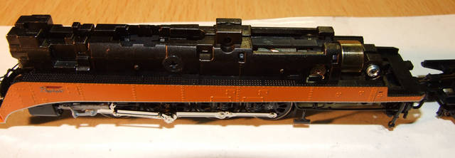
Initially I tested the loco on DC to ensure that it ran smooth. Now for the fun part.
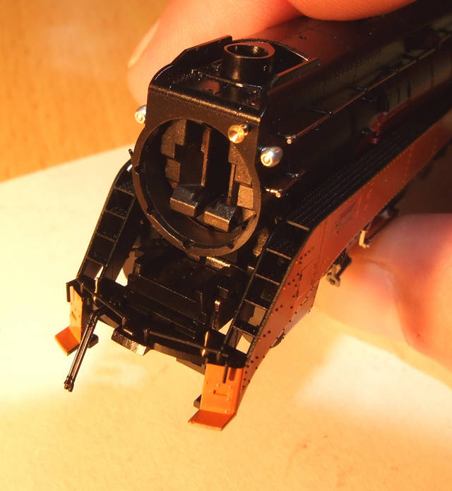
Disassembly:1. Remove smoke box door with light housing - just pulls forward.
2. Remove boiler shell and cab by lifting the boiler shell where it joins to the cab. You will find that both will come off together. When removing the boiler you'll find that you will need to lift the rear of the boiler quite high to get the front of the boiler past the bell (located on the floor of the pilot).
3. Remove the bell, Pilot floor, front coupler and cow catcher.
4. With the loco upside down remove the ash pan side panels. Be careful that you don't damage any of the piping.
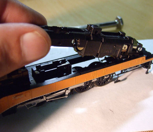
5. Remove the 4 screws holding the motor frame to the lower pickup frame (2 located center top & 2 located lower rear). Ensure you don't mix up the 2 upper screws with the lower screws which are longer.
6. Remove the front light board then lift the front of the upper frame first then gently lift the rear, sliding the upper frame forward. It should separate from the lower frame quite easily. You will also find that the tender will disconnect from the loco. Remove the drive worm retaining clip, then gently ease the drive plus universal out of the drive tower.
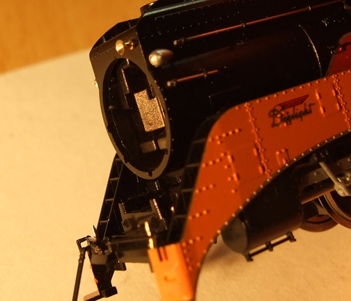
7. Now remove the skirt assembly by lifting the rear of the assembly while wriggling the front of the assembly over the light tower.
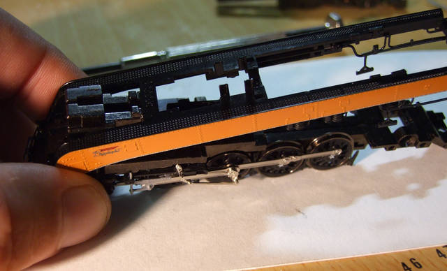
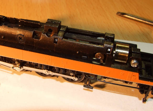
8. You now end up with the upper assembly with motor. It's now just a matter of cleaning the driver wells with alcohol, letting them dry and covering the affected areas with Kapton tape. The following photo shows the driver wells with Kapton tape applied.
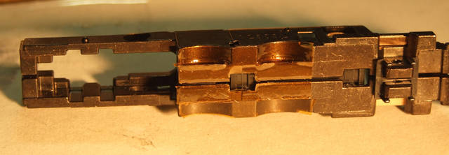
9. You now need to test the mod. Temporarily replace the upper frame (without the skirt assy) onto the lower frame. Whilst compressing the rear drivers, ensure that there is no connectivity between the wheel flanges and upper frame. Also check for no connectivity when moving the drivers from side to side. Once you are happy with this it's time to reassemble.
 Reassembly:
Reassembly is generally the reverse of the above.
1. Replace the skirt assy by angling it over the light tower.
2. Refit the upper frame to the lower frame by sliding the rear of the frame under the rear of the skirt. You will have to spread the skirt sides a bit to get the upper frame sitting flush with the lower.
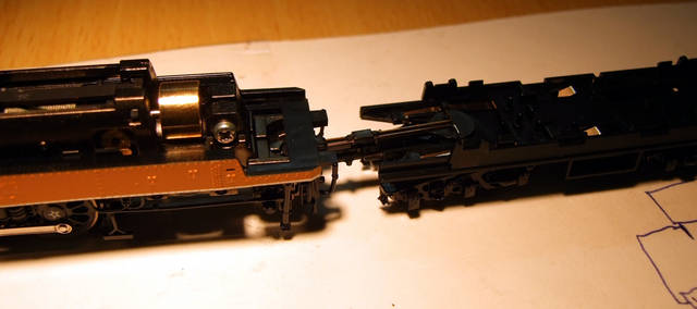
3. Reattach the tenders dual draw bars. You will have to spread the rear of the frames to insert the draw bars. I sometimes wish I had another pair of hands!
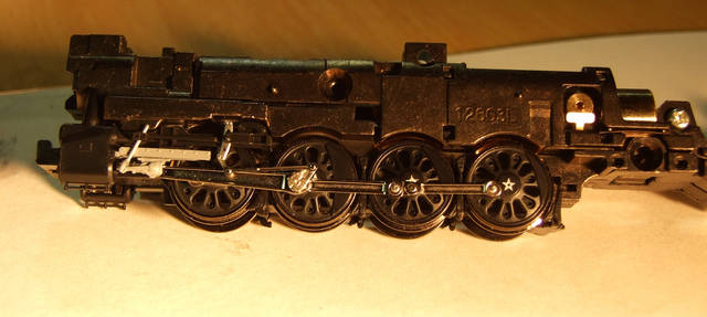
4. Tighten the 2 (short) upper screws and 2 (longer) lower screws. Don't forget the plastic washers.
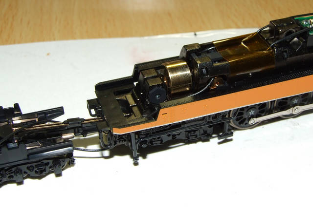
You should end up with this:
5. Refit the worm and universal assembly. I found this to be a bit tricky, but using a pair a bent nose tweezers to align the universal while seating the 2 bearing blocks eventually had the little bugger back where should be. Now refit the worm cover...just snaps in.
Light BoardAs I don't want to run more then 2 extra wires from the tender to the loco, I decided that modifying the light board would be the way to go. The Tsunami in the tender will only control the upper Mars light, while the lower will stay connected to the rails. I also replaced the orange SMD leds with white items.
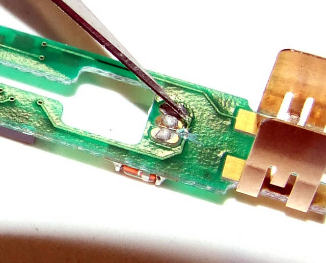
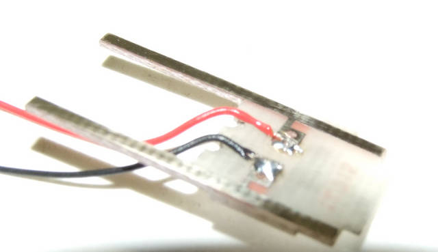
The light board mod was relatively easy to accomplish. I first de-soldered both SMD leds and replaced them with the new white items. I then de-soldered the large IC located near the front of the, then cut the trace going from the center pad on the underside of the board. This left me with a couple of nice pads to solder the decoder leads to.
Modified board
Cut this trace on the underside
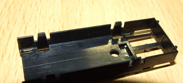
Next step is to remove the molded on posts in the tender
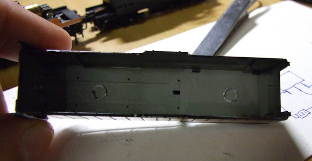
Then cut down the weight cradle so the the speaker assembly can be fitted. I also removed about 3/4 of the metal weight.
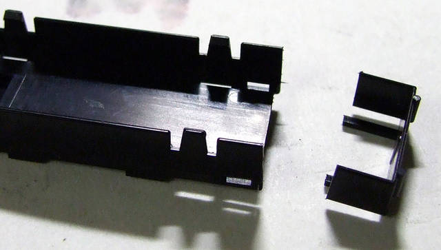
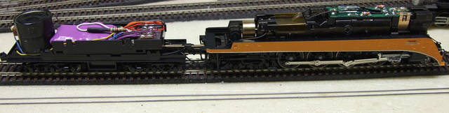
Here's the tender with speaker and decoder to ensure that I get the placement of components correct.
Now, on to the juicy part!
Solder 2 wires to the middle and right solder pads of the light board. Thread the 2 wires back along the frame, then through the 2 motor brush openings. Carefully route the wires down the rear of the frame out towards the tender.
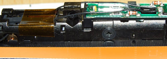
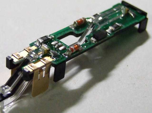
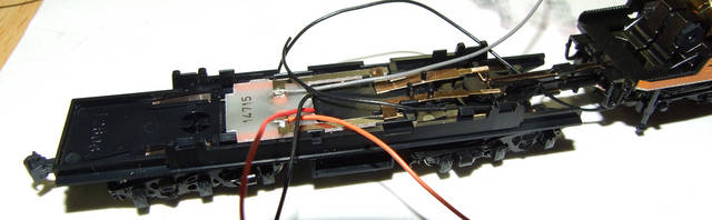
I'm utilising the original Kato analogue power board in the tender to transfer track and motor power to the decoder. First thing to do is drill out the 2 holes in the board. This is to cut continuity from the lower traces to the upper. Next thing to do is to file 2 notches in the fwd portion of the board to allow the track pick up wires to thread through.
Carefully refit the power board ensuring that none of the wires get caught. This is how it looks prior to the weight cradle being refitted.
Drill a 5mm hole in the cradle just to the rear of the steel weight. This will enable the wires to be threaded from the board through the weight cradle into the tender.
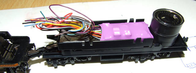
Insert all of the wires ensuring that the 2 fwd headlight don't get mixed up with the black track connection. You'll have to move the wires around to ensure that the cradle sits flush with the tender frame.
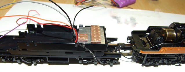
In the photo above you will see 2 pieces of PCB which are glued to the top of the steel weight. One with 6 pads and one with 2. In Aus we call this bread board, I assume that other countries have a similar product. This allows me to remove the decoder without having pull the entire tender apart.
Solder the red and black wires to the first 2 pads on the bread board, followed by the orange and gray leads on pads 3 and 4.
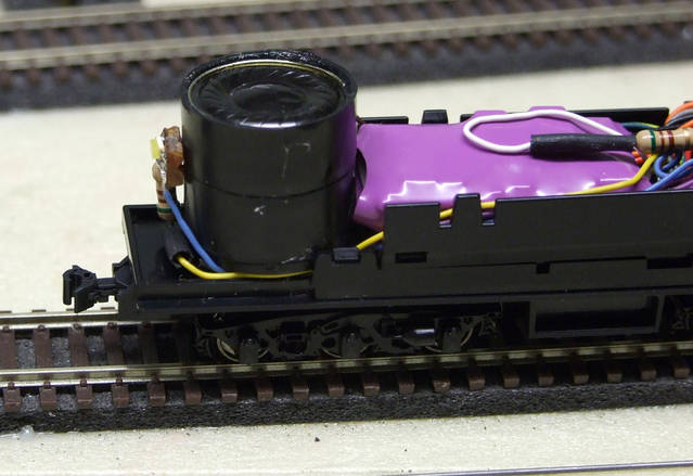
I soldered 2 purple wires to the speaker then sealed it and the speaker enclosure with silicone. Attach the assy to the rear floor of the tender with some double sided tape and run the wires forward, soldering them to the PCB.
The 2 black headlamp wires are soldered to the smaller PCB.
Next, cut the red, black, orange and gray decoder leads leaving 1.25" Solder these leads to the corresponding pads on the PCB.
Cut the blue lead from the decoder ensuring that it has enough length to reach the small PCB. Using the discarded blue wire, twist and solder it to the blue wire you just cut. Solder the 2 joined blue wires to the headlight pad on the small PCB and run the longer one back to the rear of the tender. ( I hope this makes sense?) Solder the white wire with a dropping resistor to the headlight pad on the small PCB.
Solder the 2 purple speaker leads to their corresponding pads
Last but not least is the rear tender light. I used a small peice of bread board with 2 tracks. I soldered an SMD led across the 2 tracks with a dropping resistor also soldered to one of the tracks. I then connected the decoders blue and yellow leads to this assy.
Test the newly installed decoder on the programming track, ensuring that you get a good decoder read.
Re-assemble the loco boiler, cab and pilot details, replace the tender shell and customise the programming to you needs. I'm also going to add some Loon Soft Weight (Moldable tungsten) just forward of the speaker enclosure. This will ensure that the tender is evenly balanced.
This would have to be one of the longest but extremely enjoyable installs I have ever done. The Tsunami sounds incredible, even with the small 1/2" speaker.
Finished

Amendment: As I was lowering the tender shell, I found that the speaker assembly was a tad to tall! When I did the test fit I didn't take into account the thickness of the foam double sided tape...duh! Anyway the fix was pretty easy. Just lay the speaker assembly on its side and glue a small styrene post on the center rear of the tender chassis to support the backup light. I'll take another photo and post it up soon.


