The FVM GP60M is a wonderful locomotive with the exception of the ditch lights. Their illumination is virtually nonexistant. This will remedy that issue.
You will need the normal complement of tools, and the LEDs and wire for them, and a function DCC plug in decoder.
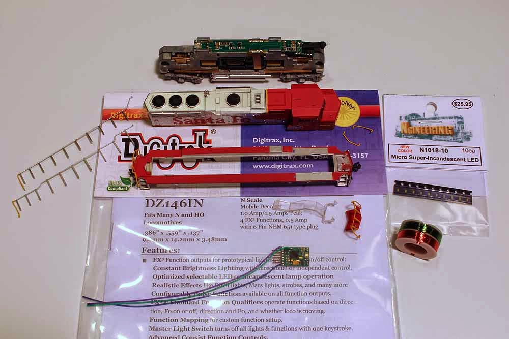
I used the Ngineering N-1018 Micro Super Incandescent LED, and their #38 Magnet Wire with solder-strippable insulation.
Additionally, since the DCC decoder for the GP60M (and indeed all FVM locos to date) is the six pin decoder (Digitrax DZ126IN), there are no functions available. But Digitrax has taken care of this with their DZ146IN which has wires for two functions. (We'll need only one function for the LEDs.)
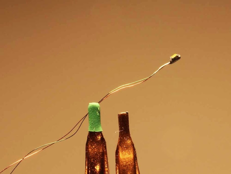
You'll prepare the LEDs per Ngineering's instructions. WARNING! This is VERY fine work - but if I can do it, so can you.
You will need to have both wires exit the LED on one end, since you will be inserting it into the hole on the underside of the porch formerly used by the light pipe.
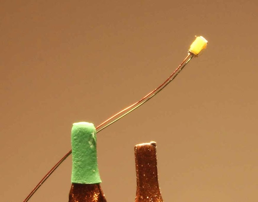
After soldering the wires in place on the LEDs you will also want to paint the LED with first black paint (to insulate), then with silver to mask the light output. You will paint five sides, leaving only the front unpainted - again, very delicate. If you don't paint, the residual light from the LED will cause the ditchlight housings to glow in a very unprototypical manner.
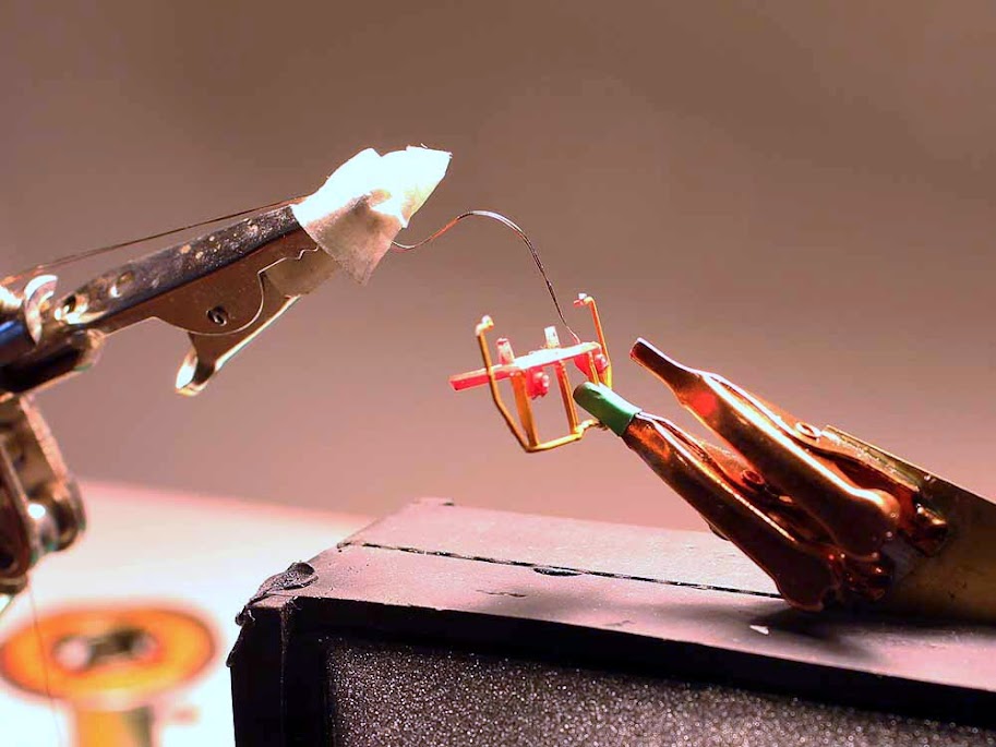
Also, test the LEDs at every step. Nothing is worse than having one or both not work when everything has been put back together. I use a 1K resistor both for testing and as a final resistor for both LEDs.
You will want to dissassemble the loco removing the walkway from the body. When you remove the "front porch" and ditch light pipe, you may discard the light pipe.
What you will have then is the front porch and front railing, with the ditch light housings. The housings have a hole where the light pipe used to go. One of my locos had that pipe glued in but it drilled out easily. You will need to enlarge the hole so the LEDs will slide in - I find a #55 bit works. You will likely have to go a little deeper so the LED goes completely in - you'll know when if you have the LED lit when inserting. You don't want to see the top edge of the LED.
Ngineering has recently changed the size of these LEDs, enlarging them slightly. A #60 bit used to do the job for the old version, the new requires a #55 hole.
Once you're happy with the position of the LED, glue it in place with some Aleene's Tacky Glue (or your glue of choice; I chose Aleene's because if you need to remove the LED after the glue has set you can do so fairly easily).
Although the pictures show the ditch light lenses in place, I have removed them on the final version. I think it looks better.
Route the wires toward the back and use a spot of glue to hold them - there's a molded channel in the walkway piece, try to route the wires so they will be within that channel when the assembly is put together.
continued


