It's tough in this economy to spend "too much" extra on our hobbies and trying to get the most bang for your buck is important.
In business I tend to invest money and not time in the things that can become solutions. In my hobby however it's the exact opposite. I can spend time but I would prefer to not spend money. So that's why I'd like this to become a SIMPLE viable solution with a price you can't beat.
My goal with this lil' experiment was to pick up where Max left off over on the Atlas board forums.
http://forum.atlasrr.com/forum/topic.asp?ARCHIVE=true&TOPIC_ID=43820&whichpage=1The Goal:To find a cheap and readily available motor with some good torque and a higher than 3v operating potential that will last as long as our locomotives will last. In a perfect world we would get this motor to perform at a constant set voltage with the gear head on for ~100-120 hours. If we can get more that's wonderful but i'm happy with the 100+ hr. mark at a constant voltage. That seems to me the ultimate stress test because we tend to run our models much slower than the full throttle will go. So having the motor/gear head run long and hard means we can (in real life) expect longer life than the tests show.
Having said, that lets modify a gear head and motor.
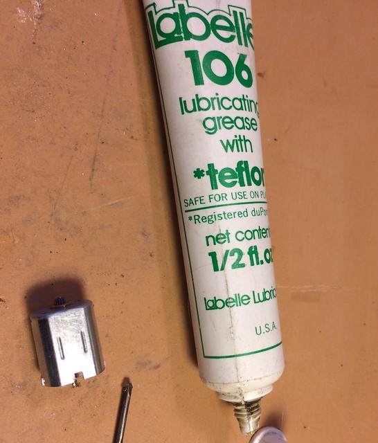
PLEASE NOTE: these are very very verbose instructions. It really is a pretty simple process I'm just trying to be thorough.Our test subject
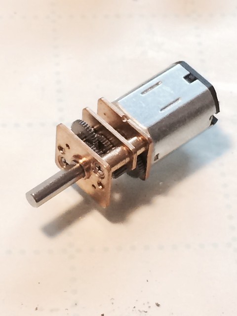 Motor modifications: (total time :08-:12 minutes)Note: You need to do the motor brush modifications with the gear head removed. I didn’t do this in the pics and had to remove it after the fact.
1.
Unscrew the gear head from the motor.
2. Optional: Mark the positive terminal on metal motor casing (optional - for posterity).3.
Bend the tabs to get the rear motor brush cap off. Remove brush cap from metal motor casing.
4.
Add NON-ACID flux to BACK side of wipers (the back side is the side that doesn't come in contact with the commutator).
5. Tin your solder iron with SILVER BEARING SOLDER.
Apply the tinned solder iron to the back side of the finger brushes that you just used the FLUX on. DO NOT USE LOW TEMP ROSIN CORE SOLDER this will "gunk" up the brushes and eventually melt.
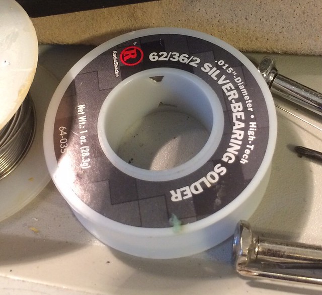
WHY SILVER BEARING SOLDER?
In short because it is much more strong and heat resistant than regular tin based solder. If the motor during operation becomes too hot (i.e. has too much voltage applied to it) the SILVER BEARING SOLDER will re-liquify and splatter all over the internal motor case. So I would recommend HIGH TEMP silver bearing solder (if you can find some, it will have a higher concentration of silver). The solder I tested (Radio Shack Silver Bearing solder) melts to the solder iron at around 430-450 degrees.
6. If you want you can repeat steps 3 and 4 to get more solder built up on the back of the brushes. I am not sure this is necessary (and haven't tested this - but in theory it should dissipate more heat - which is good).
7. Optional (I have yet to test this): Reinforce brushes with Phosphor bronze material.
Tin a piece of phosphor bronze strip material and then apply the phosphor bronze piece to the back of the finger brushes as a reinforcement. - I would love it if someone wanted to "go there".
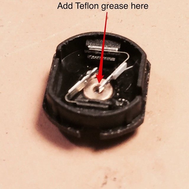
8. Optional (highly recommended):
Place grease in brush cap shaft bearing.
Place some teflon grease in the bearing of the brush cap between the 2 finger brushes where the back side of the shaft rests.
8.
Place brush cap back on motorReplace brush cap back on motor CAREFULLY. The trick to this part is to place the brush cap on until there is some push back from the commutator. Then twist the motor shaft a quarter turn right turn and then a quarter turn left WHILE GENTLY PUSHING down the brush cap. This helps seat the brushes back onto the commutator. When the brush cap is back on DO NOT PUSH THE TABS of the metal MOTOR CASING back YET.
9.
VERY IMPORTANT: Test the motorTest the motor to make sure the brushes are touching the motor commutator. If it doesn't run then pull the brush cap back off and push in the bushes toward each other. If it's not running then the motor brushes (one or both) aren't touching the commutator. The brushes are springy so this should be a simple push of the brushes towards each other.
10. If it's running fine then
grab some pliers and push the motor casing tabs back over the brush cap to secure it back down.
11.
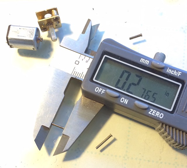
Test the motor starting voltage after running it forward and backward for 2 minutes at 3-5v. It should start spinning at around .65-.8 volts. Record this number we will refer to it later.
Congratulate yourself - You've completed the motor revamp.
 Gearhead modifications (time depends - should be about :20-:30 mins):
Note: These steps are done with the gear head removed from the motor until told otherwise.
1.
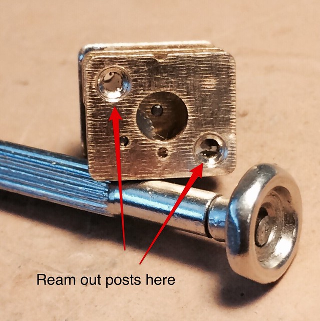
Apply ACC (EPOXY has a better longevity in my tests) to the faceplate part of the gear head (the end of the gear head that the shaft pokes out of) to the post sleeves (you should be gluing 2 brass posts). This is done to strengthen and keep the gear head straight during and after the disassembly/reassembly. In my pics I used used solder but I think this is overkill. We just want the post and sleeve to not come apart. So use some thin ACC or EPOXY.

2.
Use a drill to ream out the posts that are closest to the motor faceplate - so we can disassemble the gear head.
3. Carefully
take apart the gear head. Leaving the brass posts attached to the shaft end plate of the gear head (you should have glued these to the shaft faceplate - but in case you skipped that step).
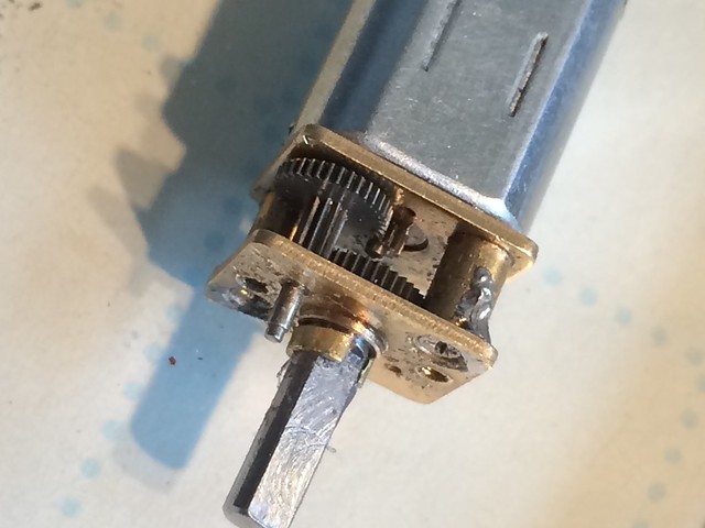
 BEFORE PERFORMING THE NEXT STEP
: if you need the motor shaft to be smaller in diameter than the 2mm or 3mm it currently is then modify the shaft here now before proceeding. This is easily done by placing the staff end of the gear in a drill chuck and placing a file against it to make it a smaller diameter when the drill is powered on.
4.
Remove the shaft from the gear head and grind off the extra staff post from the shaft gear making it smooth and flush with the gear. There should be the [----shaft----] [gear] and no staff protruding after it.

5. We also need to
ream out the hole where our new gear with the long shaft will fit. Use a small round needle file for this task it will only take a few passes. Check your progress often because you don't want to make the hole too big or the gear will wobble and that's bad.
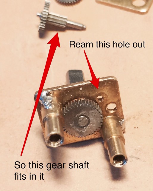
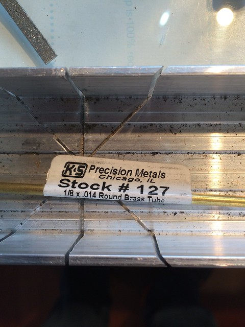
6. If your gear head shaft is 3mm in diameter on your gear head -
cut 2-3mm length of 1/8" dia. brass tubing.
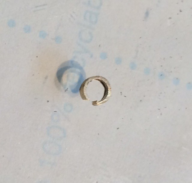
7. Since we have ground off the post at the back of the gear shaft we need some way to keep the shaft from pushing back into the gear head body.
Cut the 2-3mm long brass tubing down the middle (I used rail nippers) so it can expand and fit around the shaft. This piece will act as a shaft retainer to eliminate the "play" in the shaft and keep it snug against the shaft sleeve of the gear head.

8.
Place the shaft gear back into the gear head body.
9.
Apply EPOXY to the shaft where the retaining tube will sit on the shaft.
10.
Slide the retaining tube onto the shaft so it reaches the shaft sleeve and sits tightly but freely on the shaft against the shaft sleeve. You may get some EPOXY in between the sleeve and the shaft. So while the EPOXY is setting up just turn the shaft periodically. NOTE: Be careful to twist the shaft perpendicular don't put pressure against the shaft causing it to go out of concentricity.
11. Next step is to
shorten the brass posts since we're making the gear head shorter. Mark the posts - so there is only 1 mm of post material sticking out beyond the sleeve. This is going to attach to the gear head back plate. This will eliminate an unnecessary stage in the gear head. Remove the portion of the brass posts to your mark. I used a small circular sander to shorten the post. Brass is soft this is easy. A dremel cutoff would work too I bet.

12. We need to slightly
chamfer (round off) the portion of the gear that connects to the shaft gear. I put the gear into my drill and held a file between the chuck and the gear. When you have the gear rounded off use a dremel cutoff disc to get rid of the extra length of the post. When its assembled there should be no shaft sticking out.

13. Next you need to
cut the screw length back. I made them .275-.276 in long.
14.
Place the rear faceplate back onto the gear head making sure the holes for the gears line up properly. Test the gear head operation before screwing it back onto the motor.
15.
If the gear head is smooth, screw the gear head back onto the motor and test the motor and gear head by turning the shaft. If everything went according to plan the gear head should turn freely. Apply some oil to the gears to make things a little more frictionless.
Note: Tighten the screws down so the gearhead is snug do not over tighten the gearhead or it will bind and not turn freely.
16.
Hook it up to some DC power and see how it runs. I pulled and bent on the brass faceplates to adjust them depending on how the gears were turning you may need to do the same thing (your mileage may vary).
Very important: In my tests the motors starting voltage should only be ~0.2v difference from the motor only start voltage.
So if the motor only starting voltage was 0.7v then your starting voltage with the gearhead on ideally would be 0.8-0.9v. If it's more than that then the gear head isn't performing optimally and your motor body will be warm to the touch when voltage is applied. If this happens tweak on the face plates to get things to loosen up. If you can easily turn the gear shaft by head when its attached to the motor then you likely are fine.
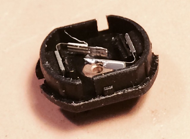
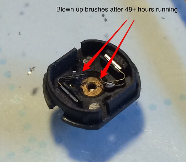
** MOTOR TEST update **My first test with this setup was run at 9v for 48+ hours. I say 48+ because at 48 hours it was running and at 60 hours mark it wasn't. So it failed somewhere in the 49-60 hour mark.
At 9v over a 48-50 hour period, in my first test motor, the friction and arcing did eventually melt the solder and the small finger brushes failed. It looked as if a shot gun had blown them up (see below). So there is a fine balance between voltage and brush failure with this method. See also how the plastic pads melted. It was just too much heat/voltage. I have some other motor brush manipulation ideas but it was a respectable length of time given I over-volted (is that a word) it.
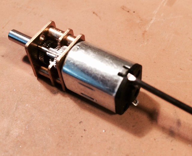
The next test (which will be done with the motor used in these pictures) will be to run it at 6v with the exact same modification of gear head and motor. I personally believe that if we can get a $5 motor and gear head to work for many remotoring situations then we will be better off (it may be more work than it’s worth but worth a try).
My hope in posting all this R&D is to get others involved and find a workable solution that doubles the life of the brushes on this motor. The gear head itself has over 120 hours on it across 3 motors. So that modification is pretty solid. You may need to re-glue the retainer clip of the motor shaft but I think using epoxy there instead of ACC would be better. I have run 3 motors out to their end of life and each has lasted 48+, 65, and 40 hours. I think the 40 hours motor was an anomaly but have a plan of testing all 10 motors I purchased (hopefully it won’t take that many).
Let's see what you all can come up with now. Let's make this happen cap'n(s). Ask whatever questions you may have. Why am I going through all this trouble? I'm a tinkerer like most of you. This is fun and may bear fruit.


